Utilisation d'une TI 84 en terminal
From Eric
m |
m |
||
| Line 11: | Line 11: | ||
La calculatrice dispose de deux ports bidirectionnels en collecteur ouvert (fil rouge et fil blanc). La transmission d'un bit se fait en positionnant l'un des fils au niveau haut et en récupérant l'accusé de réception sur l'autre fil. Il semble que les niveaux soient TTL. | La calculatrice dispose de deux ports bidirectionnels en collecteur ouvert (fil rouge et fil blanc). La transmission d'un bit se fait en positionnant l'un des fils au niveau haut et en récupérant l'accusé de réception sur l'autre fil. Il semble que les niveaux soient TTL. | ||
| - | On trouve [http://jonimoose.net/calcstuff/tilp/docs/linkguide/hardware.html ici] une description des | + | Parmi les sources d'information utiles : |
| + | * On trouve [http://jonimoose.net/calcstuff/tilp/docs/linkguide/hardware.html ici] une description des ports et des signaux. | ||
| + | * [http://www.ticalc.org/archives/files/fileinfo/294/29418.html linkport.zip] contient un tutoriel détaillé sur l'utilisation du port série. On y trouve notamment la table suivante qui donne notamment les niveaux de tension : | ||
| + | |||
| + | Writing Reading Hardware | ||
| + | $D0 %1101.0000 $C %0000.1100 Tip = +5v Ring = +5v | ||
| + | $D1 %1101.0001 $8 %0000.1000 Tip = +0v Ring = +5v | ||
| + | $D2 %1101.0010 $4 %0000.0100 Tip = +5v Ring = +0v | ||
| + | $D3 %1101.0011 $0 %0000.0000 Tip = +0v Ring = +0v | ||
| + | |||
| + | |||
| + | On trouvera [http://www.ticalc.org/pub/text/calcinfo/82-ports.txt ici] une description du protocole de bas niveau : | ||
----------------------------------------------------------------------------- | ----------------------------------------------------------------------------- | ||
| Line 98: | Line 109: | ||
=== Côté calculatrice === | === Côté calculatrice === | ||
| - | Du côté de la calculatrice, il va s'agir de transmettre et recevoir des flux émis par le micro-contrôleur. La calculatrice dispose de fonctions (en basic) permettant de transmettre une variable, une liste, etc. Cependant, ces données sont transmises selon un protocole particulier qui permet (notamment) de connaître la nature du flux, sa taille, etc. On trouve de l'information sur le format de trames sans avoir à faire trop de rétro-ingénierie, par exemple [ | + | Du côté de la calculatrice, il va s'agir de transmettre et recevoir des flux émis par le micro-contrôleur. La calculatrice dispose de fonctions (en basic) permettant de transmettre une variable, une liste, etc. Cependant, ces données sont transmises selon un protocole particulier qui permet (notamment) de connaître la nature du flux, sa taille, etc. On trouve de l'information sur le format de trames sans avoir à faire trop de rétro-ingénierie, par exemple [http://www.ticalc.org/cgi-bin/zipview?text/calcinfo/ti_protocol.zip;ti_protocol/ti83/Protocol83.txt Protocol83.txt] (L'archive [http://www.ticalc.org/archives/files/fileinfo/113/11382.html ti_protocol.zip] contient le détail des protocoles pour un ensemble assez large de calculatrices TI.) |
Or, si je veux utiliser la calculatrice comme un terminal, je veux pouvoir émettre et recevoir des flux composés uniquement d'octets "utilisateur". La solution consiste à implémenter dans l'interface un bout de logiciel qui va convertir un format dans l'autre. C'est faisable, assez simple, mais il y a plus simple. | Or, si je veux utiliser la calculatrice comme un terminal, je veux pouvoir émettre et recevoir des flux composés uniquement d'octets "utilisateur". La solution consiste à implémenter dans l'interface un bout de logiciel qui va convertir un format dans l'autre. C'est faisable, assez simple, mais il y a plus simple. | ||
| Line 227: | Line 238: | ||
jp (hl) | jp (hl) | ||
| - | Voici des explications détaillées et complémentaires sur le sujet, issues de []. | + | Voici des explications détaillées et complémentaires sur le sujet, issues de [???]. |
Revision as of 12:50, 16 June 2012
Contents |
Objectifs
L'objectif est d'utiliser une calculatrice TI82-stats comme terminal de debug de mes montages à microcontrôleurs, en lieu et place de mon vieux portable.
En pratique, il va s'agir de réaliser une petite interface matérielle et logicielle permettant de transformer un flux au format électrique et logique "texas" en en flux au format RS232 TTL.
Réalisation
Adaptation des signaux électriques
La calculatrice dispose de deux ports bidirectionnels en collecteur ouvert (fil rouge et fil blanc). La transmission d'un bit se fait en positionnant l'un des fils au niveau haut et en récupérant l'accusé de réception sur l'autre fil. Il semble que les niveaux soient TTL.
Parmi les sources d'information utiles :
- On trouve ici une description des ports et des signaux.
- linkport.zip contient un tutoriel détaillé sur l'utilisation du port série. On y trouve notamment la table suivante qui donne notamment les niveaux de tension :
 Writing	Reading					Hardware
 $D0	        %1101.0000	$C	%0000.1100	Tip = +5v	Ring = +5v
 $D1	        %1101.0001	$8	%0000.1000	Tip = +0v	Ring = +5v
 $D2		%1101.0010	$4	%0000.0100	Tip = +5v	Ring = +0v
 $D3		%1101.0011	$0	%0000.0000	Tip = +0v	Ring = +0v
On trouvera ici une description du protocole de bas niveau :
 -----------------------------------------------------------------------------
 Port 0 : Link port                                                       R/W
 -----------------------------------------------------------------------------

 This port is used to communicate with other calculators, computers and CBL
 equipment. The port is used in the same ways as the link port on the TI85.

 The port consist of two parts, the Port Configuration Register (PCR) and the
 Port Data Register (PDR). PCR controls whether the PDR is used as input or as
 an output (PCRx controls PDRx). PDR is used to send and receive data.

 Bit  Function
 --------------------------------------------------------------------
  7   PCR3
  6   PCR2
  5   PCR1
  4   PCR0
  3   PDR3
  2   PDR2
  1   PDR1
  0   PDR0

 PDR bit 0 and 2 is used to control/read the voltage on the tip, while bit 1
 and 3 is used for the middle. The base is always used for ground.

 Normally PCR is set to C0 by the ROM, which sets PDR0/1 as inputs and PDR2/3
 as outputs. Doing this means that the voltage at the tip and the middel can
 be read as PDR1/0. PDR2/3 is then used to control the output (a one gives an
 output of app.
 When two calculators are connected together the output will be high if neither
 of them has their transistor on, otherwise it will be low (wired or)

 Write:
 ------

 When writing to the link port the upper nibble sets the PCR, while the lower
 sets the PDR. The state of the tip and the middle can be set using the
 following values.

 Value  Function
 ----------------------------------------------------
 C0     White wire is positive. Red wire is positive.
 D4     White wire is positive. Red wire is grounded.
 E8     White wire is grounded. Red wire is positive.
 FC     Whits wire is grounded. Red wire is grounded.

 The above values are the values used by the ROM, except for FC which is not used
 since the system never sets both wires to ground. Other values can be used, but
 these gives the best results.

 Read:
 -----

 When the a byte is read from the link port, the upper nibble contains the last
 value written to the PCR. Assuming that these are set to 1100b (e.g. one of the
 above mentioned values where written to PCR), the contence of the PDR can be
 interpeted as follows.

 Bit  State Function
 ------------------------------------------------------------------------
 2+3        Last value written
 1    1     White wire is positive.
      0     White wire is grounded.
 0    1     Red wire is positive.
      0     Red wire is grounded.
L'interface hardware est chargée de transformer le flux en provenance de la calculatrice en un flux série standard. L'idée est d'utiliser un port d'entrée et un port de sortie par fil (on pourrait n'utiliser qu'un port par fil mais : ça complique vaguement le logiciel et n'importe quel microcontrôleur disposant de voies d'entrées / sorties série dispose aussi d'un nombre plus que suffisant de ports.
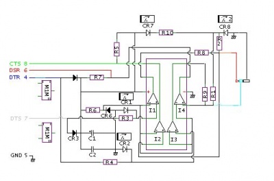
L'interface matérielle est la suivante (c'est un peu luxueux, on pourrait faire plus simple) :
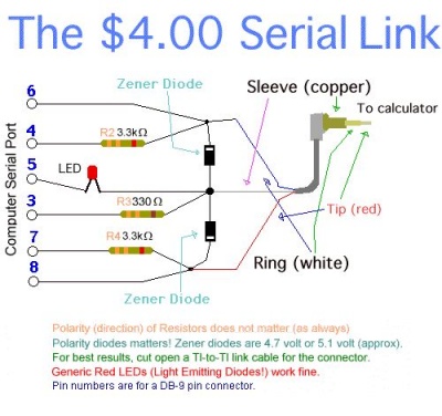
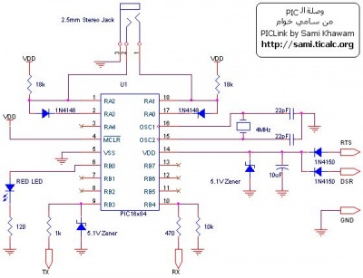
Naturellement, on trouve bien des montages sur internet :
- Le fameux $4 serial link (et d'autres solutions) dont voici le schéma :
- Le modèle de Sami qui utilise un microcontrôleur. Voici le schéma :
Le logiciel
Côté calculatrice
Du côté de la calculatrice, il va s'agir de transmettre et recevoir des flux émis par le micro-contrôleur. La calculatrice dispose de fonctions (en basic) permettant de transmettre une variable, une liste, etc. Cependant, ces données sont transmises selon un protocole particulier qui permet (notamment) de connaître la nature du flux, sa taille, etc. On trouve de l'information sur le format de trames sans avoir à faire trop de rétro-ingénierie, par exemple Protocol83.txt (L'archive ti_protocol.zip contient le détail des protocoles pour un ensemble assez large de calculatrices TI.)
Or, si je veux utiliser la calculatrice comme un terminal, je veux pouvoir émettre et recevoir des flux composés uniquement d'octets "utilisateur". La solution consiste à implémenter dans l'interface un bout de logiciel qui va convertir un format dans l'autre. C'est faisable, assez simple, mais il y a plus simple.
On peut en effet piloter directement, "à la main", l'interface matérielle de la calculatrice, mais il faut alors faire un peu d'assembleur Z80. On trouvera dans la rubrique Programmation assembleur de la TI84 Stats quelques explications sur les outils à utiliser et la façon de les utiliser... Le pilotage est assez simple car il se résume à des quelques "in" et "out" sur le port adéquat.
Voici, par exemple, le bout d'assembleur Z80 qui réalise les opérations d'émission et de réception d'un octet :
 ;
 ; Link routines taken from Telnet 83,
 ; Sent to me by Scott Dial <homosapian@geocities.com>.
 ; To use them call "ReceiveByte" or "SendByte". You can test the port
 ; (and receive byte if necessary) with "TryReceiveByte".

 ;       LINK PORT WRITE EQUATES
 ;
 #define		D0LD1L                    0C3h
 #define		D0LD1H                    0C1h
 #define		D0HD1L                    0C2h
 #define		D0HD1H                    0C0h
 #define		BPORT                     0

 #define	LINKMASK	12

 TryReceiveByte:
 	in	a,(BPORT)
 	and	LINKMASK
 	cp	LINKMASK
 	scf
 	ret	z
 ReceiveByteCont:
 	call	LinkPrep
 	jr	ReceiveCont
 ReceiveByte:
 	call	LinkPrep
 ReceiveBits:
 	ld	de,-1
 WaitRecBit:
 	call	CheckLink
 	jr	z,LinkFailed
 	cp	LINKMASK
 	jr	z,WaitRecBit
 ReceiveCont:
 	sub	LINKMASK/3*2
 	ld	a,LINKMASK/3*2
 	ld	d,D0LD1H
 	jr	c,ReceiveLow
 	rra
 	ld	d,D0HD1L
 ReceiveLow:
 	rr	c
 	ld	(AckBit),a
 	ld	a,d
 	out	(BPORT),a
 	ld	de,-1
 WaitAckRec:
 	call	CheckLink
 	cp	0
 AckBit =$-1
 	jr	nz,WaitAckRec
 	ld	a,D0HD1H
 	out	(BPORT),a
 	ld	d,4
 WaitReadyRec:
 	dec	d
 	jr	z,ReadyRec
 	in	a,(BPORT)
 	cp	LINKMASK
 	jr	nz,WaitReadyRec
 ReadyRec:
 	djnz	ReceiveBits
 	jr	LinkSuccess

 LinkPrep:
 	ex	(sp),hl
 	push	bc
 	push	de
 	set	indicOnly,(iy+indicflags)
 	ld	b,8
 	jp	(hl)

 SendByte:
 	call	LinkPrep
 	ld	c,a
 SendBits:
 	rr	c
 	ld	a,D0LD1H
 	jr	nc,SendLow
 	ld	a,D0HD1L
 SendLow:
 	out	(BPORT),a
 	ld	de,-1
 WaitAckSend:
 	call	CheckLink
 	jr	nz,WaitAckSend
 SendAcked:
 	ld	a,D0HD1H
 	out	(BPORT),a
 	ld	de,-1
 WaitReadySend:
 	call	CheckLink
 	cp	LINKMASK
 	jr	nz,WaitReadySend
 	djnz	SendBits
 LinkSuccess:
 	or	0
 .org $-1
 LinkFailed:
 	scf
 	res	indicOnly,(iy+indicflags)
 	ld	a,0D0h
 	out	(BPORT),a
 	ld	a,c
 	pop	de
 	pop	bc
 	pop	hl
 	ret

 CheckLink:
 	pop	hl
 	dec	de
 	ld	a,d
 	or	e
 	jr	z,LinkFailed
 	ld	a,0BFh
 	in	a,(BPORT)
 	and	LINKMASK
 	jp	(hl)
Voici des explications détaillées et complémentaires sur le sujet, issues de [???].
TI-83 Link Port
       ---------------

       This brief look at the TI-83 link port shows how to access
       the port and use it for basic sending and receiving of bytes of
       data.

       The TI-83 link port uses 2 data lines, D0 & D1, for communicating.
       These data lines are accessed through the B-port of the Z80.
       The symbol BPORT is equated to the correct port value in
       the include file "TI83ASM.INC".

       Note :  THE DATA LINES ARE READ IN AS HIGH (1) WHEN NO

               ACTIVITY IS PRESENT ON THE DATA LINES.

               THE LOWER 2 BITS OF THE B-PORT, BITS 0 AND 1, ARE FOR
               WRITING TO THE DATA LINES.

               BITS 2 AND 3 OF THE B-PORT ARE FOR READING IN THE STATUS
               OF THE DATA LINES.


       Reading the data lines :


               IN      A,(BPORT)       ; READ THE VALUE OF THE B-PORT
               CP      0Ch             ; ANY DATA LINE GO LOW ?
               JR      Z,NO_ACTIVITY   ; IF READ 0Ch THEN NO LINES LOW

               CP      8               ; IS D0 PULLED LOW ?
               JR      Z,D0_LOW        ; YES, BIT 2 = 0 SO D0 IS LOW NOW
              ;
              ; ELSE BIT 3 WAS LOW (ACC=4), SO D1 IS LOW
              ;


       Writing to the data lines :

               There are symbols equated to the correct values
               to "OUT" to the B-PORT for controlling the
               status of the data lines.

               LD      A,D0LD1L

               OUT     (BPORT),A    ; is used for setting D0 low, D1 low

               LD      A,D0LD1H
               OUT     (BPORT),A    ; is used for setting D0 low, D1 high

               LD      A,D0HD1L
               OUT     (BPORT),A    ; is used for setting D0 high, D1 low

               LD      A,D0HD1H
               OUT     (BPORT),A    ; is used for setting D0 high, D1 high


       A few of the TI-83 system routines concerning the link port

       are availble for ASM use. These routines are accessed by making
       a call to the routine _IO_EXEC, with a value stored in the
       byte at ASM_IND_CALL (808Ch).

       _IO_EXEC = 51EFh

       D0LD1L      EQU              0C3h
       D0LD1H      EQU              0C1h
       D0HD1L      EQU              0C2h
       D0HD1H      EQU              0C0h
       BPORT       EQU              0

       ASM_IND_VALUE
       -------------

           19d         REC1STBYTE : This routine goes into idle
                                    or low power mode and waits for
                                    the data lines to change. Then
                                    reads a byte of data using the TI-83
                                    bit protocol. This only reads the 1st
                                    byte of data. The byte is returned
                                    in the accumlator.
           20d         REC1STBYTENC : The same as REC1STBYTE except
                                      that the cursor does not flash.
                                      The byte is returned in the
                                      accumulator.
           22d         RECABYTE     : This routine looks at the data
                                      lines for activity for about
                                      2 seconds and reads in a single
                                      byte of data. If no data is found
                                      an error will be generated.
                                      The byte is returned in the
                                      accumulator.
           11d         SENDABYTE    : This routine sends a byte of
                                      data across the data lines
                                      using the TI-83 bit protocol. If
                                      there is no response within about 2
                                      seconds an error is generated.
                                      The data to be sent needs to be in
                                      the accumulator.
Côté microcontroleur
Le code C suivant est extrait du site jonimoose] déjà cité.
 /*
 Send a byte to the calculator
 */
 int put92(char data)
 {
   int bit;
   for(bit=0; bit<8; bit++)
   {
       if(data & 1)
       {
           outportb(lpt_out, 2);
           while((inportb(lpt_in) & 0x10) == 1);
           outportb(lpt_out, 3);
           while((inportb(lpt_in) & 0x10) == 0);
       }
       else
       {
           outportb(lpt_out, 1);
           while((inportb(lpt_in) & 0x20) == 1);
           outportb(lpt_out, 3);
           while((inportb(lpt_in) & 0x20) == 0);
       }
       data >>= 1;
   }
 }

 /*
 Reads a byte from the calculator
 */
 unsigned char get92(void)
 {
   int bit;
   unsigned char v, data=0;

   for(bit=0; bit<8; bit++)
   {
       while((v = inportb(lpt_in) & 0x30) == 0x30);
       if(v & 1)
       {
           data = (data >> 1) | 0x80;
           outportb(lpt_out, 1);
           while((inportb(lpt_in) & 0x20) == 0x00);
           outportb(lpt_out, 3);
       }
       else
       {
           data = data >> 1;
           outportb(lpt_out, 2);
           while((inportb(lpt_in) & 0x10) == 0x00);
           outportb(lpt_out, 3);
       }
   }
 }
Conclusion
Voici le résultat :
<à compléter>


