Quoi de neuf 2015
From Eric
(Difference between revisions)
m |
m |
||
| Line 8: | Line 8: | ||
For 2015, everything is described below... | For 2015, everything is described below... | ||
| - | + | == March 2016 == | |
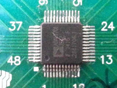
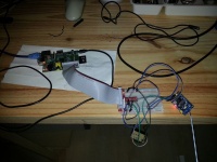
| + | * Yes! I have managed to solder my 0.5 pitch ADAU1701 using my brand new hot-air soldering station. The result is pretty good even though I had to remove a few solder bridges. Here it is: [[File:adau1701_solder.jpg|400px|thumb|none]] | ||
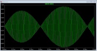
| + | * I have also completed the board that hosts the ADAU1701 DSP and... it works pretty well. Here is a picture of the DSP generating sinusoidal and triangular waveforms: | ||
| + | [[File:adau1701_waves.jpg|400px|thumb|none]] from the following design (in AD's SigmaStudio):[[File:adau1701_sswaves.jpg|400px|thumb|none]] | ||
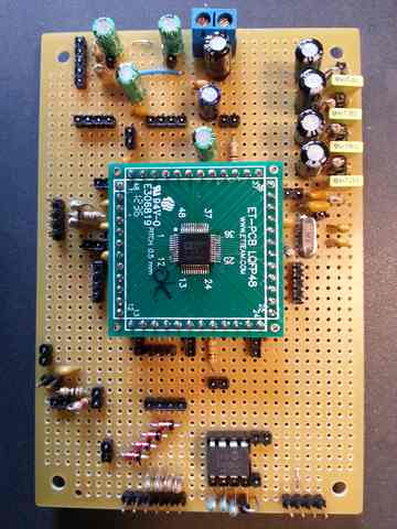
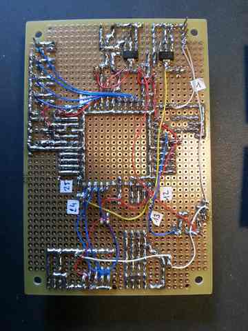
| + | * Here is the board: [[File:adau1701_board_up.jpg|400px|thumb|none]][[File:adau1701_board_dn.jpg|400px|thumb|none]] | ||
== February 2016 == | == February 2016 == | ||
* I have bought a cheap frequency generator (Feeltech FY3200S) and a hot-air soldering station (Aoyue int 852): | * I have bought a cheap frequency generator (Feeltech FY3200S) and a hot-air soldering station (Aoyue int 852): | ||
Revision as of 02:30, 1 April 2016
Experiments carried out in the past (from 2011) are described hereafter:
"Quoi de neuf" means "What's new"...
For 2015, everything is described below...
Contents |
March 2016
- Yes! I have managed to solder my 0.5 pitch ADAU1701 using my brand new hot-air soldering station. The result is pretty good even though I had to remove a few solder bridges. Here it is:

- I have also completed the board that hosts the ADAU1701 DSP and... it works pretty well. Here is a picture of the DSP generating sinusoidal and triangular waveforms:


- Here is the board:


February 2016
- I have bought a cheap frequency generator (Feeltech FY3200S) and a hot-air soldering station (Aoyue int 852):


- I have managed to solder a 0.8 TQFP64 chip (an Atmega 128) using hot air. The result is pretty nice event though I had to remove 4 bridges. This success came after a first trial (with the same type of chip) which ended badly: one dead Atmega and a lost TQFP adapter.
- The key to success was:
- to solder at 350°C (I guess that this is slightly higher than actually necessary)
- to place the chip on the board, stick it with some Kapton tape, and then
- to put as little as possible soldering paste. (I think that putting the paste once the chip is in place prevents it migrating behing the pins where it could create short circuits. Well, it could possibly be removed afterwards using alcohol or aceton...)
- to use a medium nozzle (i.e., not the smallest)
- to remove the remaining bridges between pins using some desoldering wick and a large soldering tip (and not my Hakko-clone with its tiny tip).
- Here is the result: not too bad... This was a test run before I receive my tiny ADAU1701 (with a 0.5 pitch).

It took me more time than when I use my soldering iron but the result is nicer.
January 2016
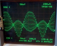
- After watching this very interesting video about the Gilbert cell, I have built the following mixer (the schematics comes from the video)
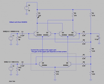
- As I have used non matched transistors, the mixing is not as symetric as it should be !


December 2015
- I have managed to build a Linux kernel for my ZTurn Zynq board. The current status of the operations is given here.
- Playing with the RPi GPIOs, SPI and CAN: I have managed to drive a MCP2515 CAN controler (through SPI). My RPI is now able to communicate with its Arduino cousins via CAN. It is worth noting that everything can be done in user space, including handling interrupts (thanks to sysfs and poll(2) system call).
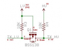
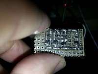
- Beware of electrical levels: the CAN controler is 5V while the RPI is 3.3. I have built a 3.3<=>5v converter using a few BSS138 and >10K resistors (search for "AN10441 Level shifting techniques in I2C-bus" by NXP.com or Adafruit's level shifter). The schema is the following: . Soldering SMT's is not that difficult but the result looks terrible.
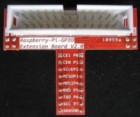
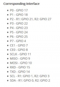
- Connector P1:
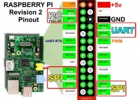
- The P1 breakout board has the following pinout:
- Activating the SPI is achieved using
- Connector P1:


sudo raspi-config
- and (possibly) removing the spi_bcm2708 from the blacklist (comment out the corresponding line):
sudo nano /etc/modprobe.d/raspi-blacklist.conf
- GPIO lines can be accessed from a shell script. For instance, switching ON/OFF GPIO4 is achieved as follows:
 cd /sys/class/gpio
 echo 04 > export
 cd gpio4
 echo out > direction
 echo 1 > value
 echo 0 > value
November 2015
October 2015
September 2015
August 2015
July 2015
Playing with buildroot and my Raspberry Pi...
June 2015
Nothing.
May 2015
Nothing.
April 2015
No time to do anything about "real electronics".
A few things, anyway:
- I have bought a new RPI 2, installed opencv on it and done a few experiments about line following using Canny and Hough. The idea is to be able to run some benchmark to compare performances of the PI with respect to a Zynq.
- About the Zynq... I have also bought a Zynk board at MyIR. A nice little thingie comes with 1GiO of SDRAM, a Zynq XC7Z020 and many devices (Ethernet, Usb, a buzzer, a CAN adapter, etc.). The board comes with Ubuntu pre-installed. My objective is to run some hard/soft combination at bare metal level. Hopefully, I have found a nice tutorial here.
Building an application on the Zynq is quite complicated since you have to generate the configuration of the FPGA (the bitstream), a FSBL, a specific BSP, your application... to end up with the "boot.bin" file that is loaded by the board. Hopefully, Xilinx' Vivado hide most of the details. It is nice as long as it works...
- I have done a few experiments using SystemC and SystemC AMS (the analog part). You would certainly not replace Spice by SystemC AMS, but SystemC TLM + SystemC + SystemC AMS makes it possible to model and simulate a complete system at different levels of abstraction / models of computation.
March 2015
(see above)
February 2015
(see above)
January 2015
- 10/01/2015
- I have started a small experiment with sound synthesis chips. Right now, I have hooked a YM2612 to an Atmega. My objective is to be able to read and play VGM files.
- To familiarize myself with VGM, I am writing a small VGM parser in Python.
- There are quite a large number of sound synthesis chips: SN76482, the Yamaha family (YM2608, YM2612, YM2149, YMF262, etc.), the AY-3-8912, etc. Wikipedia has a very good set of articles about those sound chips.