RobotAspi
From Eric
(Difference between revisions)
m |
m |
||
| Line 1: | Line 1: | ||
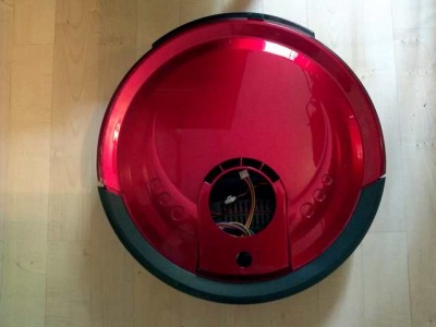
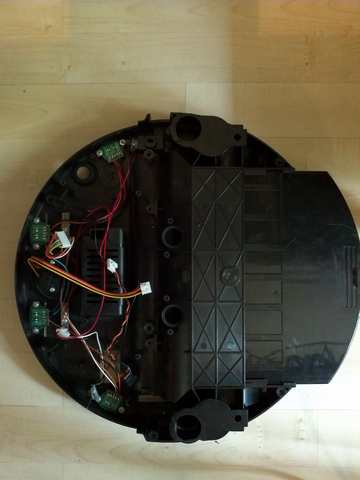
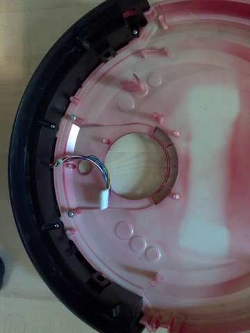
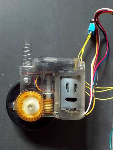
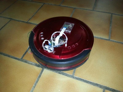
A few pictures of the recycling of my vacuum cleaner robot: | A few pictures of the recycling of my vacuum cleaner robot: | ||
| - | + | = The initial robot = | |
[[File:aspirobot_1.jpg|400px|thumb|none]] | [[File:aspirobot_1.jpg|400px|thumb|none]] | ||
[[File:aspirobot_2.jpg|400px|thumb|none]] | [[File:aspirobot_2.jpg|400px|thumb|none]] | ||
[[File:aspirobot_3.jpg|400px|thumb|none]] | [[File:aspirobot_3.jpg|400px|thumb|none]] | ||
[[File:aspirobot_4.jpg|400px|thumb|none]] | [[File:aspirobot_4.jpg|400px|thumb|none]] | ||
| + | = The "power" board = | ||
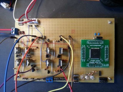
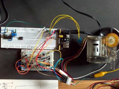
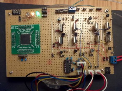
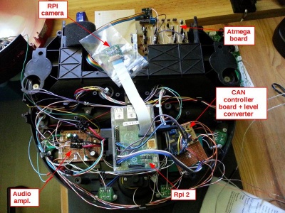
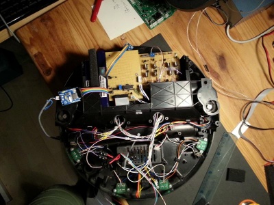
| + | This board uses an Atmega microontroller. It is in charge of all I/Os (including motor control). The board is fitted with two full H-bridges (one per motor). It communicates with the man board (a raspberry Pi 2) via a CAN network. | ||
[[File:aspirobot_5.jpg|400px|thumb|none]] | [[File:aspirobot_5.jpg|400px|thumb|none]] | ||
[[File:aspirobot_6.jpg|400px|thumb|none]] | [[File:aspirobot_6.jpg|400px|thumb|none]] | ||
| Line 11: | Line 13: | ||
[[File:aspirobot_completed2.jpg|400px|thumb|none]] | [[File:aspirobot_completed2.jpg|400px|thumb|none]] | ||
[[File:aspirobot_completed3.jpg|400px|thumb|none]] | [[File:aspirobot_completed3.jpg|400px|thumb|none]] | ||
| - | = A small TDA 2030 audio amplifier | + | = A small TDA 2030 audio amplifier = |
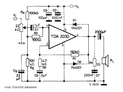
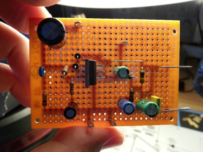
Note that I have slightly modified the schema given in the datasheet: I have added a 220nf capacitor and a 150K ohm (in series) on the feedback (pin 4 to pin 2). | Note that I have slightly modified the schema given in the datasheet: I have added a 220nf capacitor and a 150K ohm (in series) on the feedback (pin 4 to pin 2). | ||
[[File:aspirobot_audio_amp1.jpg|400px|thumb|none]] | [[File:aspirobot_audio_amp1.jpg|400px|thumb|none]] | ||
[[File:aspirobot_audio_amp2.jpg|400px|thumb|none]] | [[File:aspirobot_audio_amp2.jpg|400px|thumb|none]] | ||
Revision as of 20:11, 13 August 2016
A few pictures of the recycling of my vacuum cleaner robot:
The initial robot
The "power" board
This board uses an Atmega microontroller. It is in charge of all I/Os (including motor control). The board is fitted with two full H-bridges (one per motor). It communicates with the man board (a raspberry Pi 2) via a CAN network.
A small TDA 2030 audio amplifier
Note that I have slightly modified the schema given in the datasheet: I have added a 220nf capacitor and a 150K ohm (in series) on the feedback (pin 4 to pin 2).
