Linky
From Eric
(Created page with "The documentation about the Linky TIC protocol can be found in the [https://www.enedis.fr/media/2035/download ENEDIS CPT manual]. The TIC interface is composed of three lines (A...")
Newer edit →
Revision as of 15:24, 25 September 2021
The documentation about the Linky TIC protocol can be found in the ENEDIS CPT manual.
The TIC interface is composed of three lines (A, L1,L2).
The signals are at 50KHz.
The (A,L1) lines can be used to power a device. The voltage is 6Vrms (max 13V) with a maximum power of 130mW.
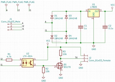
I use (A,L1) to power the CubeCell that implements the TIC-to-LoRa gateway. The setup (that can be found at many places over the Internet) simply use a full bridge rectifier (using 1N4008 diaodes) and a 7905 regulator. The 5V voltage is thenused to chrage a small LiPo battery which is finally used to power the CubeCell (the CubeCell has a battery interface). I could have used a supercapacitor, but I only have a LiPo battery on hand at that time...
The TIC data are transmitted on (L1,L2) using a 1200bds serial protocol. Details about the frame format can be found in the Enedis documentation (see above).
Inorder to be used by the CubeCell, the (L1,L2) signal at 50Khz must be filtered and converted into a 3.3V signal.
This is done using a LTV814 optocoupler. The bandwidth of the optocoupler is sufficiently low to filter the 50Kz signal.
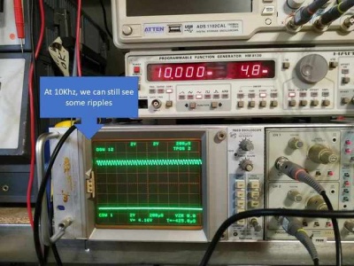
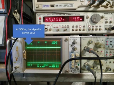
Here are picture of the output of the optocoupler when the input is driven by a 10KHz signal and a 50Khz signal:
At 50Khz, there are no more ripples on the output.
The schematics of the interface is given below (copied from here).


