ADAU1701 DSP Board
From Eric
Create the design with SigmaStudio
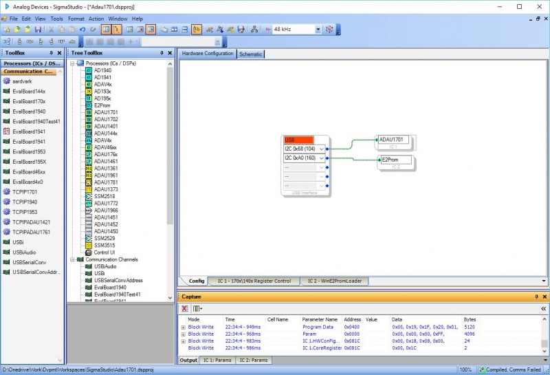
The first thing to do is to create the configuration:
This configuration contains a E2PROM block because I use a self-booting configuration.
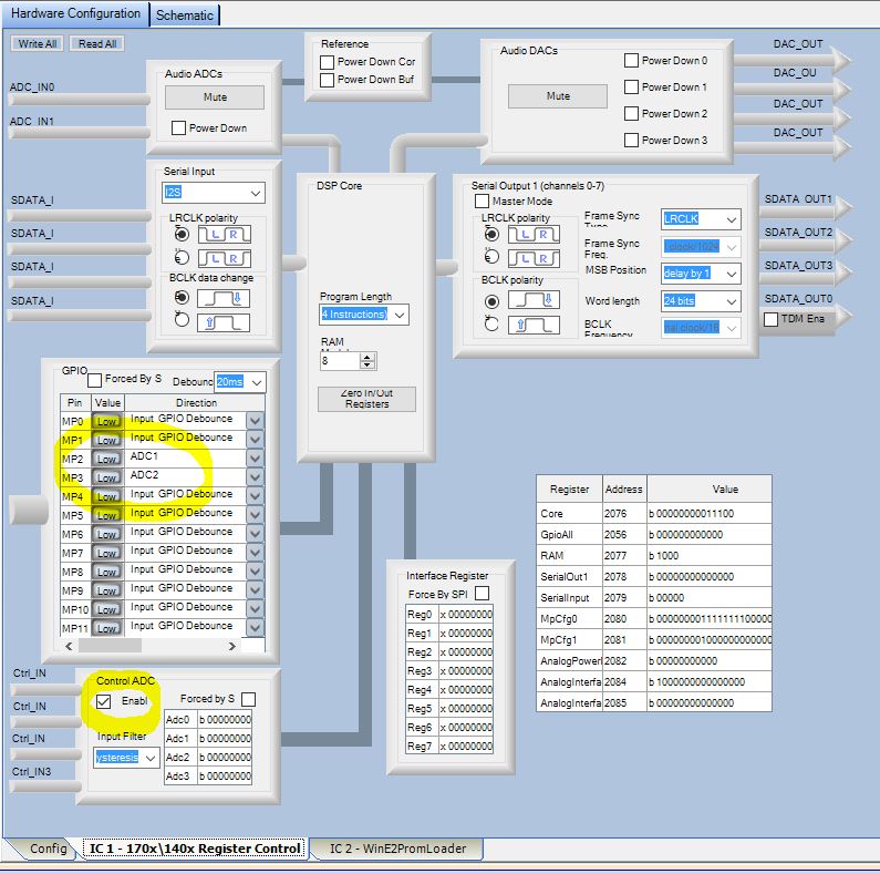
Once the configuration is done, you can configure the ADAU1701 using the IC1 register control tab (at the bottom of the Harware configuration page):
You can see that I have configured two inputs, MP2 and MP3 as analog input using ADC1 and AD2. Be careful: a subset of the inputs can be connected to a subset of the ADCs.
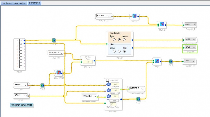
Once the ADAU is configured, you can create the schematic. My test schematic is given below:
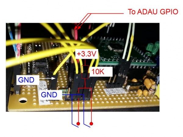
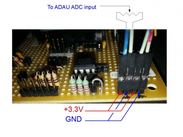
This one is for test purposes: I use two push buttons (UP/DN) to control the volume (PushVol1) of the signal sent to the DAC1 output. The first button is also connected to the "ChimeWG1" block that generates a chime sound when pressed. This sound is mixed to the input so that when I press it, the beep is superimposed to the music. The volume of the beep is controled by a potentiometer connected to the ADC2.
I have also used:
- A block that generates a chorus effect (block VChor1) that is sent to DAC3 and DAC2.
- A block that generates a frequency as a function of the position of the potentiometer connected to the ADC1.
Transfert the design to the EEPROM
Once the file is "compiled", it has to be programmed into the 24LC64 EEPROM.
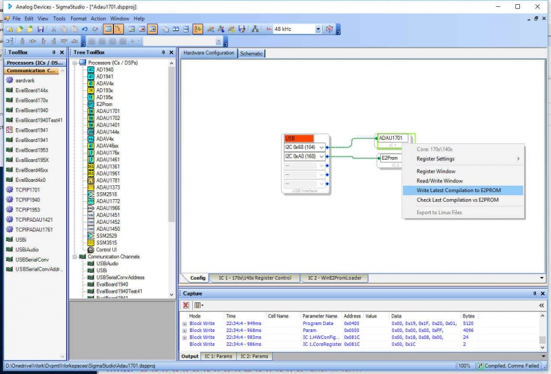
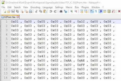
First, open the E2PROM.Hex file that has been created using the "Write Latest Compilation to E2PROM" command (right click on the ADAU1701 block in the "hardware configuration" panel).
This file is located in the directory associated with the E2PROM block. In my design, the directory is called "Adau1701_IC 2" for a E2Prom block called "IC 2".
A typical example is shown below.
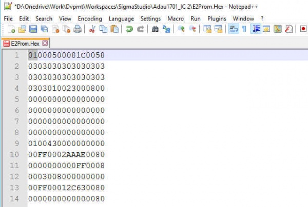
This ASCII file has to be transformed into a 16-bit Intel file to be written on the E2PROM. First, I remove all "0x" and " , " and ", " from the file. The result is shown below.
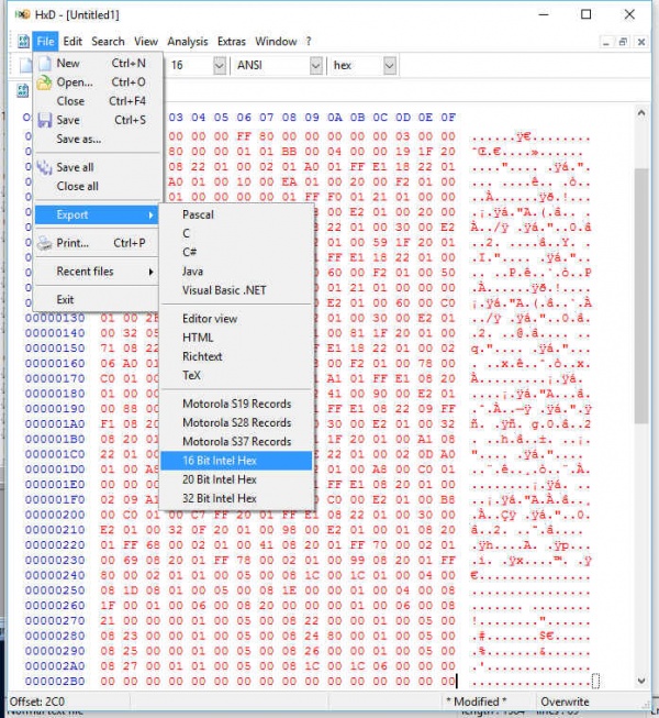
The file can then be transformed into the Intel format. I use the HxD editor to to this/ I copy the content of the modified hex file and paste it into a file created into HxD and export it using the 16-bit Intel format, as shown below:
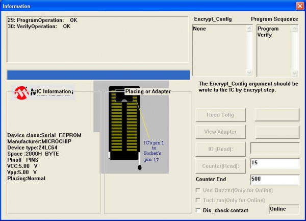
The exported file can be loaded with the E2PROM programmer.
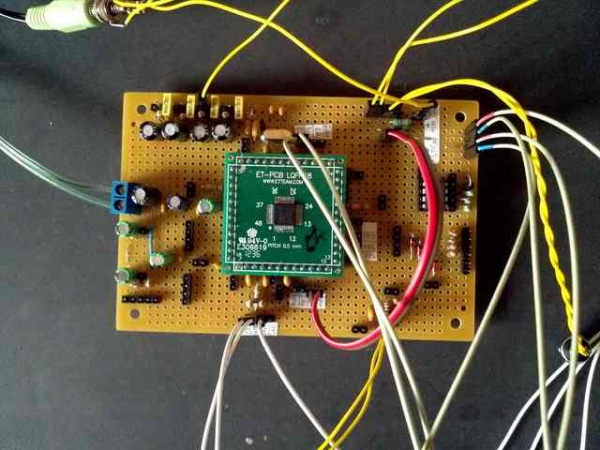
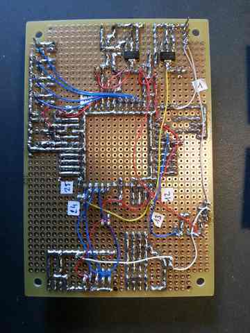
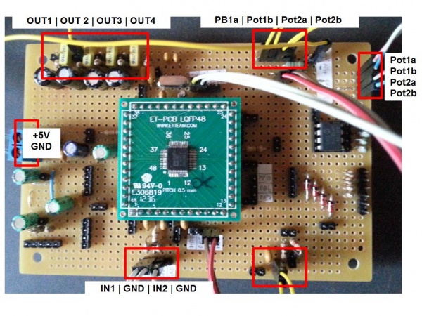
The hardware platform (for my personal records)
Top view:
Bottom view:
Close view of the push-buttons connector:
Close view of the potentiometers connector:
View of all connectors:
