Oscilloscope
From Eric
m |
m |
||
| Line 6: | Line 6: | ||
* https://www.circuitstoday.com/crt-cathode-ray-tube | * https://www.circuitstoday.com/crt-cathode-ray-tube | ||
* https://www.aplustopper.com/cathode-ray-oscilloscope-construction-working/ | * https://www.aplustopper.com/cathode-ray-oscilloscope-construction-working/ | ||
| - | |||
| - | |||
The [http://www.electronixandmore.com/projects/simplescope/index.html most popular schematic], from Elextronixandmore, using a Hammond transformer. A kit can be bought at [http://www.catahoulatech.com/index.php?product=KIT-0001 Catahoula Technologies]. The schematic and the BOM are [http://www.catahoulatech.com/products/KIT-0001/OscilloscopeCrtDriverData.pdf here]. | The [http://www.electronixandmore.com/projects/simplescope/index.html most popular schematic], from Elextronixandmore, using a Hammond transformer. A kit can be bought at [http://www.catahoulatech.com/index.php?product=KIT-0001 Catahoula Technologies]. The schematic and the BOM are [http://www.catahoulatech.com/products/KIT-0001/OscilloscopeCrtDriverData.pdf here]. | ||
| Line 27: | Line 25: | ||
== Anode == | == Anode == | ||
| - | == Cathode == | + | == Cathode control == |
The intensity is controlled by the cathode voltage: | The intensity is controlled by the cathode voltage: | ||
| Line 33: | Line 31: | ||
[[File:crt-intensity-control-2.jpg|400px|thumb|none]] | [[File:crt-intensity-control-2.jpg|400px|thumb|none]] | ||
| - | == Blanking / grid == | + | On some schematics, the intensity is controled by the gate (that's a bit strange...): |
| + | |||
| + | [[File:5LO38I-hv-4.jpg|400px|thumb|none]] | ||
| + | |||
| + | == Blanking / grid control == | ||
The control grid "controls the number of electrons or, indirectly, the intensity of of emitted electrons from cathode". | The control grid "controls the number of electrons or, indirectly, the intensity of of emitted electrons from cathode". | ||
| - | From https://www.circuitstoday.com/crt-cathode-ray-tube: "The grid is kept at negative potential (variable) with respect to cathode and its function is to vary the electron emission and so the brilliancy of the spot on the phosphor screen. The hole in the grid is provided to allow passage for electrons through it and concentrate the beam of electrons along the axis of tube | + | From https://www.circuitstoday.com/crt-cathode-ray-tube: "The grid is kept at negative potential (variable) with respect to cathode and its function is to vary the electron emission and so the brilliancy of the spot on the phosphor screen. The hole in the grid is provided to allow passage for electrons through it and concentrate the beam of electrons along the axis of tube." |
| - | + | ||
| - | |||
| + | From https://www.sciencedirect.com/topics/engineering/cathode-ray-tube: "These electrons have to pass through a pinhole in a metal plate, the control grid. The movement of the electrons through this hole can be controlled by altering the voltage of the grid, and a typical voltage would be some 50 V negative compared to the cathode. At some value of negative grid voltage, the repelling effect of a negative voltage on electrons will be greater than the attraction of the large positive voltage at the far end of the tube, and no electrons will pass the grid: this is the condition we call cut-off." | ||
| - | == Focus == | + | (Note that on several diagrams, the grid is more positive than the cathode... In that case, it accelerates the electrons rather that repells them. This makes sense if the gate is not used.) |
| + | |||
| + | The gate is used for blanking (as its name implies). It is sometimes coupled to the control transistor via a capacitor (because the blanking is only necessary for a short period of time). In order to blank, the gate must be at a smaller | ||
| + | [[File:crt-gate-2.jpg|400px|thumb|none]] | ||
| + | |||
| + | == Focus control == | ||
From https://www.circuitstoday.com/crt-cathode-ray-tube: | From https://www.circuitstoday.com/crt-cathode-ray-tube: | ||
[[File:crt-focus-1.jpg|400px|thumb|none]] | [[File:crt-focus-1.jpg|400px|thumb|none]] | ||
| - | == Deviations plates == | + | == Deviations plates control == |
| + | |||
| + | [[File:deflection_1.jpg|400px|thumb|none]] | ||
| + | [[File:deflection_2.jpg|400px|thumb|none]] | ||
| Line 93: | Line 102: | ||
The datasheet can be found here : http://www.ges.cz/sheets/8/8sj31jv2.pdf | The datasheet can be found here : http://www.ges.cz/sheets/8/8sj31jv2.pdf | ||
| - | |||
| - | |||
| - | |||
| - | |||
Revision as of 16:49, 10 January 2021
Contents |
General information about CRT tubes
Some explanations about the functioning of a CRT:
- http://www.cfp-radio.com/realisations/rea75/tv2pouces-01.html
- http://speakyssb.blogspot.com/2016/08/5lo38i-crt-test.html (5LO38I tube)
- This site gives very nice diagrams and explnations about CRTs.
- https://www.circuitstoday.com/crt-cathode-ray-tube
- https://www.aplustopper.com/cathode-ray-oscilloscope-construction-working/
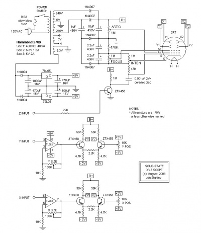
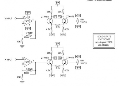
The most popular schematic, from Elextronixandmore, using a Hammond transformer. A kit can be bought at Catahoula Technologies. The schematic and the BOM are here.
Another one solid-state scope from Electronixandmore, without isolation. The voltages are the following:
 HV		350V	Anode Cap
 X1/X2/Y1/Y2	280V	Deflection plates
 A2		270V	Anode 2
 A1		-310V	Anode 1
 K		-665V	Cathode
 G1		-675V	Control Grid
Those values are fine for a 3BP1 tube.
Structure
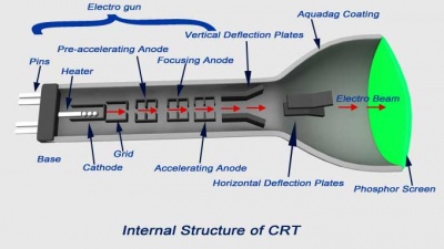
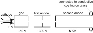
From https://www.electrical4u.com/cathode-ray-oscilloscope-cro/:
Anode
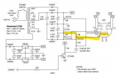
Cathode control
The intensity is controlled by the cathode voltage:
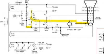
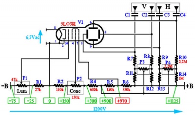
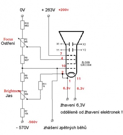
On some schematics, the intensity is controled by the gate (that's a bit strange...):
Blanking / grid control
The control grid "controls the number of electrons or, indirectly, the intensity of of emitted electrons from cathode". From https://www.circuitstoday.com/crt-cathode-ray-tube: "The grid is kept at negative potential (variable) with respect to cathode and its function is to vary the electron emission and so the brilliancy of the spot on the phosphor screen. The hole in the grid is provided to allow passage for electrons through it and concentrate the beam of electrons along the axis of tube."
From https://www.sciencedirect.com/topics/engineering/cathode-ray-tube: "These electrons have to pass through a pinhole in a metal plate, the control grid. The movement of the electrons through this hole can be controlled by altering the voltage of the grid, and a typical voltage would be some 50 V negative compared to the cathode. At some value of negative grid voltage, the repelling effect of a negative voltage on electrons will be greater than the attraction of the large positive voltage at the far end of the tube, and no electrons will pass the grid: this is the condition we call cut-off."
(Note that on several diagrams, the grid is more positive than the cathode... In that case, it accelerates the electrons rather that repells them. This makes sense if the gate is not used.)
The gate is used for blanking (as its name implies). It is sometimes coupled to the control transistor via a capacitor (because the blanking is only necessary for a short period of time). In order to blank, the gate must be at a smaller
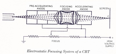
Focus control
From https://www.circuitstoday.com/crt-cathode-ray-tube:
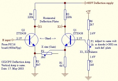
Deviations plates control
The tubes
5LO38I russian tube
I have bought a russian 5LO38I tube on ebay.
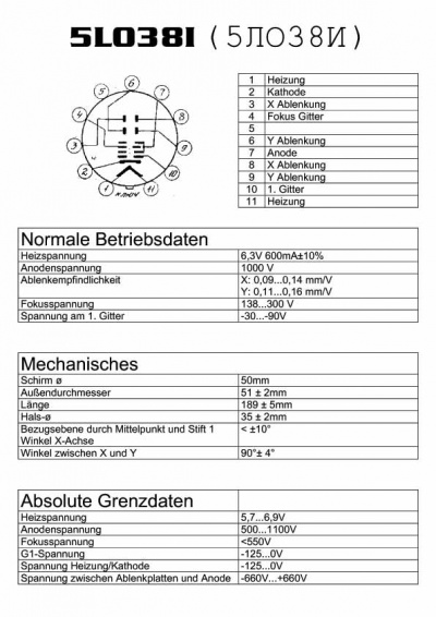
The tube is delivered with a russian notice. Hopefully, someone has provided a german translation translation:
This gives:
- Filament voltage: 6.3V, 600mA +/- 10% (5.7 to 6.9V)
- Anode voltage: 1000V (500V to 1100V)
- Deflection:
- On X: 0.09 to 0.14 mm/V
- On Y: 0.11 to 0.16 mm/V
- Focus voltage : 138V to 300V (<550V)
- Cathode voltage: (-125V to 0V)
- G1 voltage: -30V to -90V (-125V to 0V)
- Voltage between "ablenkplatten" and anode: (-660V to 660V)
You can find several applications of the 5LO38I:
- http://danyk.cz/osc_en.html
- http://speakyssb.blogspot.com/2016/08/5lo38i-crt-test.html
- http://www.emartinka.cz/index.asp?IDKategorie=9&IDClanku=18&Akce=clanek
- http://www.labguysworld.com/ES_CRT_DEFLECTION.htm
- http://users.triera.net/zupanbra/osciloskop/Mali_osciloskop.html
- http://www.webx.dk/oz2cpu/clock-scope/scope.htm
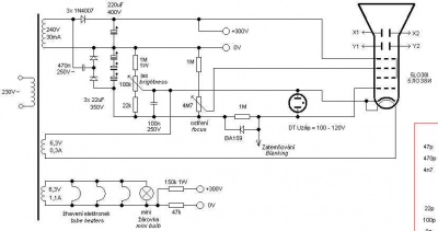
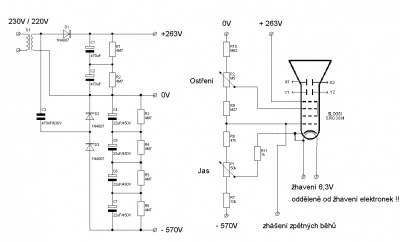
Several schematics to generate the high-voltage power supplies:
- From http://speakyssb.blogspot.com/2016/08/5lo38i-crt-test.html (inspired from http://www.emartinka.cz/index.asp?IDKategorie=9&IDClanku=18&Akce=clanek)
Chinese 8SJ31J tube
See Aliexpress (8SJ31 from GuangYi store (Aliexpress).
The datasheet can be found here : http://www.ges.cz/sheets/8/8sj31jv2.pdf
My setup
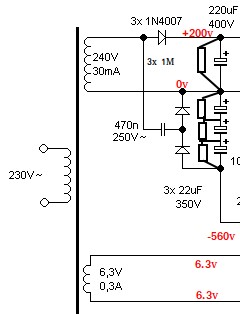
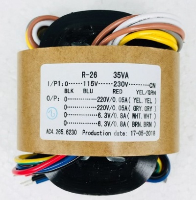
For the generation of the high voltages, I'll use a 220V/220x2+6.3Vx2 ransformer (bought on AliExpress):
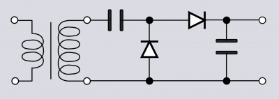
I'll use a Greinacher voltage doubler to generate the -600V. The +220V voltage will be obtained by half-rectifying the transformer's secondary output.
The Greinacher circuit:
Other schematics
- https://www.webx.dk/oz2cpu/clock-scope/scope.htm
- http://www.jogis-roehrenbude.de/Leserbriefe/Scope-Clock/Scope-Clock.htm
- https://web.jfet.org/vclk/
- http://www.catahoulatech.com/index.php?product=KIT-0001|PCB
- http://www.sgitheach.org.uk/scope2.html
- http://ludens.cl/Electron/scope/scope.html
- https://www.eevblog.com/forum/projects/oscilloscope-under-construction/
- https://www.eevblog.com/forum/projects/2-inch-video-monitor/
Other topics
Oscilloscope music:
- https://oscilloscopemusic.com/software.php (a software to generate pictures using X-X modulation))
See also:
