Oscilloscope
From Eric
On this page, I show how to control a small CRT. There is also a video (in french, sorry) here.
Contents |
General information about CRT tubes
Some explanations about the functioning of a CRT:
- http://www.cfp-radio.com/realisations/rea75/tv2pouces-01.html
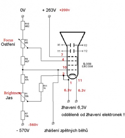
- http://speakyssb.blogspot.com/2016/08/5lo38i-crt-test.html (5LO38I tube)
- This site gives very nice diagrams and explnations about CRTs.
- https://www.circuitstoday.com/crt-cathode-ray-tube
- https://www.aplustopper.com/cathode-ray-oscilloscope-construction-working/
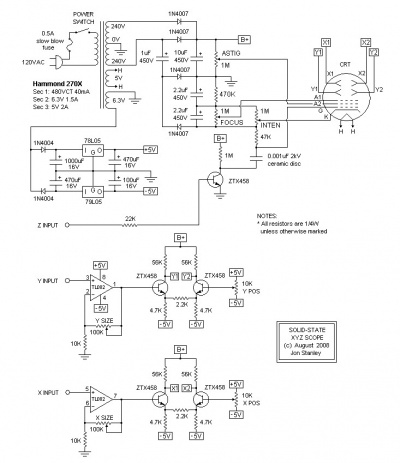
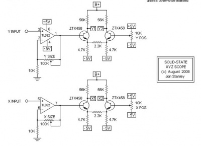
The most popular schematic, from Elextronixandmore, using a Hammond transformer. A kit can be bought at Catahoula Technologies. The schematic and the BOM are here.
Another one solid-state scope from Electronixandmore, without isolation. The voltages are the following:
 HV		350V	Anode Cap
 X1/X2/Y1/Y2	280V	Deflection plates
 A2		270V	Anode 2
 A1		-310V	Anode 1
 K		-665V	Cathode
 G1		-675V	Control Grid
Those values are fine for a 3BP1 tube.
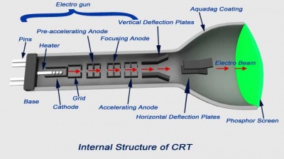
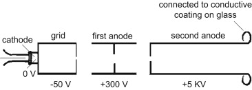
Structure
From https://www.electrical4u.com/cathode-ray-oscilloscope-cro/:
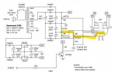
Cathode voltage
The intensity is controlled by the cathode voltage:
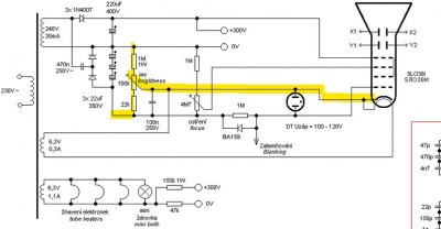
On some schematics, the intensity is controled by the gate (that's a bit strange...):
Blanking / grid voltage
(See the Wikipedia article.
The control grid "controls the number of electrons or, indirectly, the intensity of of emitted electrons from cathode". From https://www.circuitstoday.com/crt-cathode-ray-tube: "The grid is kept at negative potential (variable) with respect to cathode and its function is to vary the electron emission and so the brilliancy of the spot on the phosphor screen. The hole in the grid is provided to allow passage for electrons through it and concentrate the beam of electrons along the axis of tube."
From https://www.sciencedirect.com/topics/engineering/cathode-ray-tube: "These electrons have to pass through a pinhole in a metal plate, the control grid. The movement of the electrons through this hole can be controlled by altering the voltage of the grid, and a typical voltage would be some 50 V negative compared to the cathode. At some value of negative grid voltage, the repelling effect of a negative voltage on electrons will be greater than the attraction of the large positive voltage at the far end of the tube, and no electrons will pass the grid: this is the condition we call cut-off."
(Note that on several diagrams, the grid is more positive than the cathode... In that case, it accelerates the electrons rather that repells them. This makes sense if the gate is not used.)
The gate is used for blanking (as its name implies). It is sometimes coupled to the control transistor via a capacitor (because the blanking is only necessary for a short period of time). In order to blank, the gate must be at a smaller
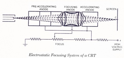
Focus voltage
From https://www.circuitstoday.com/crt-cathode-ray-tube:
Deviations plates voltages
The tubes
5LO38I russian tube
I have bought a russian 5LO38I tube on ebay.
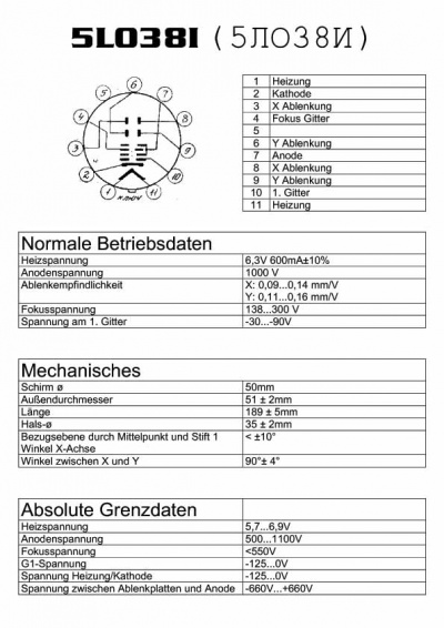
The tube is delivered with a russian notice. Hopefully, someone has provided a german translation translation:
This gives:
- Filament voltage: 6.3V, 600mA +/- 10% (5.7 to 6.9V)
- Anode voltage: 1000V (500V to 1100V)
- Deflection:
- On X: 0.09 to 0.14 mm/V
- On Y: 0.11 to 0.16 mm/V
- Focus voltage : 138V to 300V (<550V)
- Cathode voltage: (-125V to 0V)
- G1 voltage: -30V to -90V (-125V to 0V)
- Voltage between "ablenkplatten" and anode: (-660V to 660V)
You can find several applications of the 5LO38I:
- http://danyk.cz/osc_en.html
- http://speakyssb.blogspot.com/2016/08/5lo38i-crt-test.html
- http://www.emartinka.cz/index.asp?IDKategorie=9&IDClanku=18&Akce=clanek
- http://www.labguysworld.com/ES_CRT_DEFLECTION.htm
- http://users.triera.net/zupanbra/osciloskop/Mali_osciloskop.html
- http://www.webx.dk/oz2cpu/clock-scope/scope.htm
- https://www.jsykora.info/analog-curve-tracer/
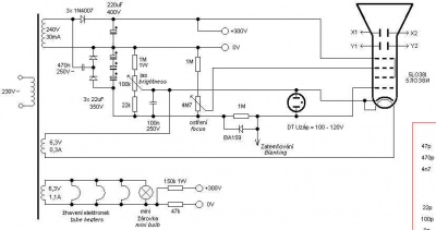
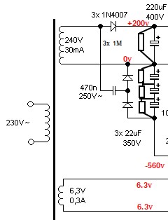
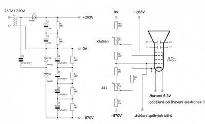
Several schematics to generate the high-voltage power supplies:
- From http://speakyssb.blogspot.com/2016/08/5lo38i-crt-test.html (inspired from http://www.emartinka.cz/index.asp?IDKategorie=9&IDClanku=18&Akce=clanek)
Chinese 8SJ31J tube
See Aliexpress (8SJ31 from GuangYi store (Aliexpress).
The datasheet can be found here : http://www.ges.cz/sheets/8/8sj31jv2.pdf
My setup
The power supplies
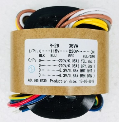
The transformer
For the generation of the high voltages, I'll use a 220V/220x2+6.3Vx2 ransformer (bought on AliExpress):
Generating V+
V+ (anode voltage) is obtained by half rectifying and filtering the transformer's 220V output using a signle diode and a pair of capacitors. I use two 680uF capacitors in series because each of them are rated for 200V only.
Generating V-
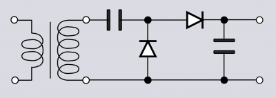
To generate the -600V (or so), I half-rectify the negative half of the 220V signal and double it using a Greinacher voltage doubler. Again, I have used two capacitors is series to handle the 600V potential (the capacitors only withstand 400V).
The Greinacher circuit:
I have also added a neon bulb in order to warn that some high voltage is present in the two big capacitors. The neon is on above 60V. Note that the charges remain quite a long time in those capacitors because they can only flow through the CRT anode. On the cathode side, the charges can flow through the voltage divider, so the capacitors empty fairly rapidly (a few seconds).
The voltage divider
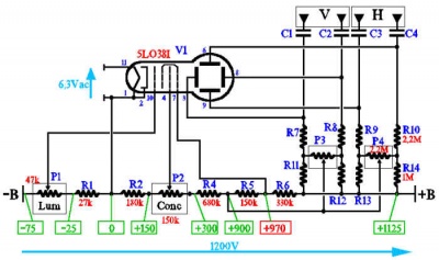
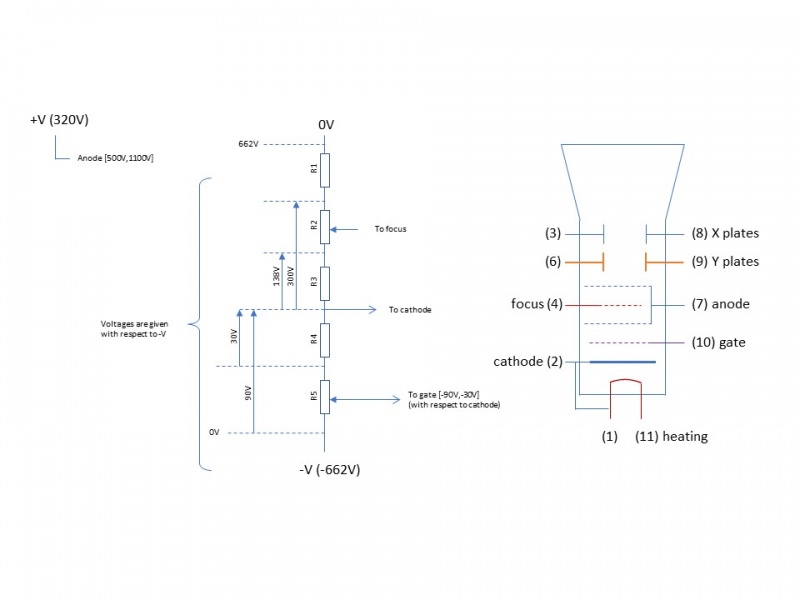
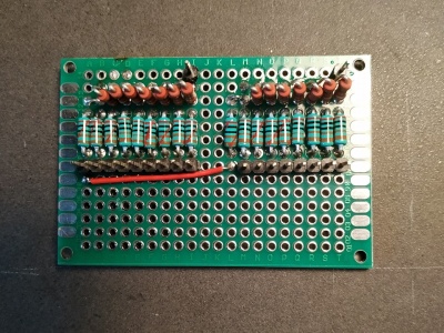
In order to generate the gate, cathode, and focus voltage, I use a simple voltage divider using a few resistors and timmers. The values of the resistors were computed as show in the following diagram:
The voltage values has been taken from the tube datasheet. Then R1 to R5 were computed as follows;
 Voltage constraints
 i(r5) = 60
 i(r5+r4)=90
 i(r3)=138
 i(r3+r2)=300
 i(r5+r4+r3+r2+r1)=662
 Let r5=47K
 i=60/47K
 r4=(47K/60)*90-47K = 23.5K # 22K (trimmer)
 r3=(47K/60)*138 = 108.1K # 100K
 r2=(47K/60)*300-100K=135K # 100K (potentiometer)+47K (trimmer)
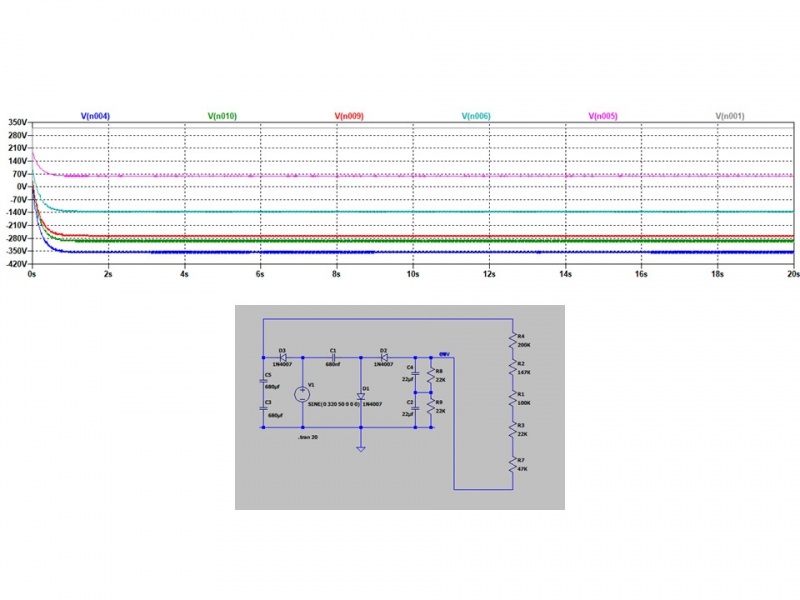
 r1=(47K/60)*662-47K-22K-100K-147K = 202K # 200K
This gives the following result:
Controling the plates
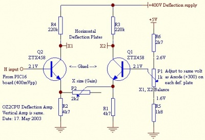
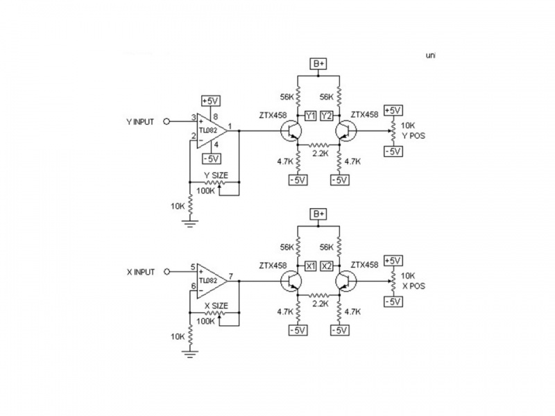
To control each pair of plates, I used two ZTX458 transistors, as proposed by (TBD):I have also used an op-amp to control the bases of the transistor; I have simply replaced the 100K potentiometer by a 22K trimmer (my microcontroller generates signal from 0 to 3.3V and I need 0 to 5v to address the complete tube).
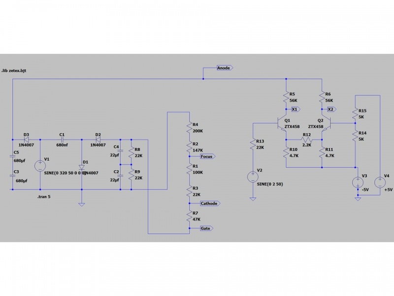
The complete schematrics (for one couple of plates and without the op-amp) is the following:
The op-amp power supply
The op-amp is powered by a symmetric -5v / +5v power supply. These voltages are generated by a couple of linear regulators (7905 and 7805):
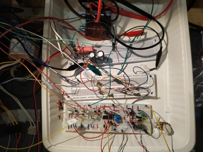
The end result (hardware)
Here is the final result:
The software part
In order to display something on the CRT, The end result (hardware), I have first used an Arduino fitted with two MCP4725 DACs. This worked correctly, but the refresh rate was much too low. With a few lines displayed, the refresh for visible (the display was flickering). So I first built a 8-bit R2R DAC
when I discovered that the ESP32 was already providing two internal 8-bits DACs...
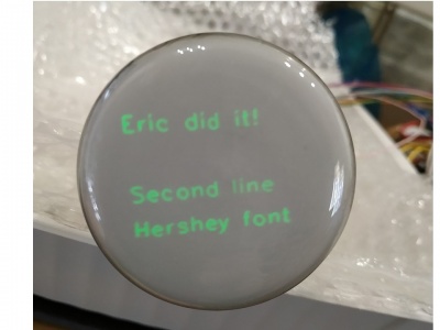
The result is pretty neat:
The control software uses a line plotting function from Alan Volke (aka w2aew) (here). To draw the characters, I use the Hershey font pdovided at http://paulbourke.net/dataformats/hershey (I have made a few simple modifications in order to reduce the size of the data structure).
Final setup
[edit 2023] I have created a PCB and put everything in a box... See here.
Other schematics
- https://www.webx.dk/oz2cpu/clock-scope/scope.htm
- http://www.jogis-roehrenbude.de/Leserbriefe/Scope-Clock/Scope-Clock.htm
- https://web.jfet.org/vclk/
- http://www.catahoulatech.com/index.php?product=KIT-0001|PCB
- http://www.sgitheach.org.uk/scope2.html
- http://ludens.cl/Electron/scope/scope.html
- https://www.eevblog.com/forum/projects/oscilloscope-under-construction/
- https://www.eevblog.com/forum/projects/2-inch-video-monitor/
Other topics
Oscilloscope music:
- https://oscilloscopemusic.com/software.php (a software to generate pictures using X-X modulation))
See also:
