ESP8266 page
From Eric
Contents |
The chip
The ESP8266 is a SoC designed by Espressif.
Someone managed to decap the chip (well, a similar one) and show its internal layout (source here):

The MCU is a Tensilica lx106 processor IP.
The board
I use the following boards:
- ESP-01:

- ESP-12e:

Connecting the ESP8266 board to a PC
The ESP-01
The main things to know for an ESP-01:
- VCC is 3.3V (NOT 5V).
- Input pins are NOT 5V tolerant.
- The power supply shall deliver at least 500mA.
- Pin CH_PD must be pulled-up to 3.3V
- Pin RST must be pulled-up to 3.3V.
The ESP8266 ESP-01 board pin-out is the following:

WARNING: GPIO16 is actually RST on my board.
The ESP-12e
Connections are identical to ESP-01 except that GPIO15 *** must be pulled-down to GND*** for the chip to work. By the way, pin "CH_PD" is named "EN" on my board:

Here is the schematics of a ESP-12e from AI Thinker (source) :
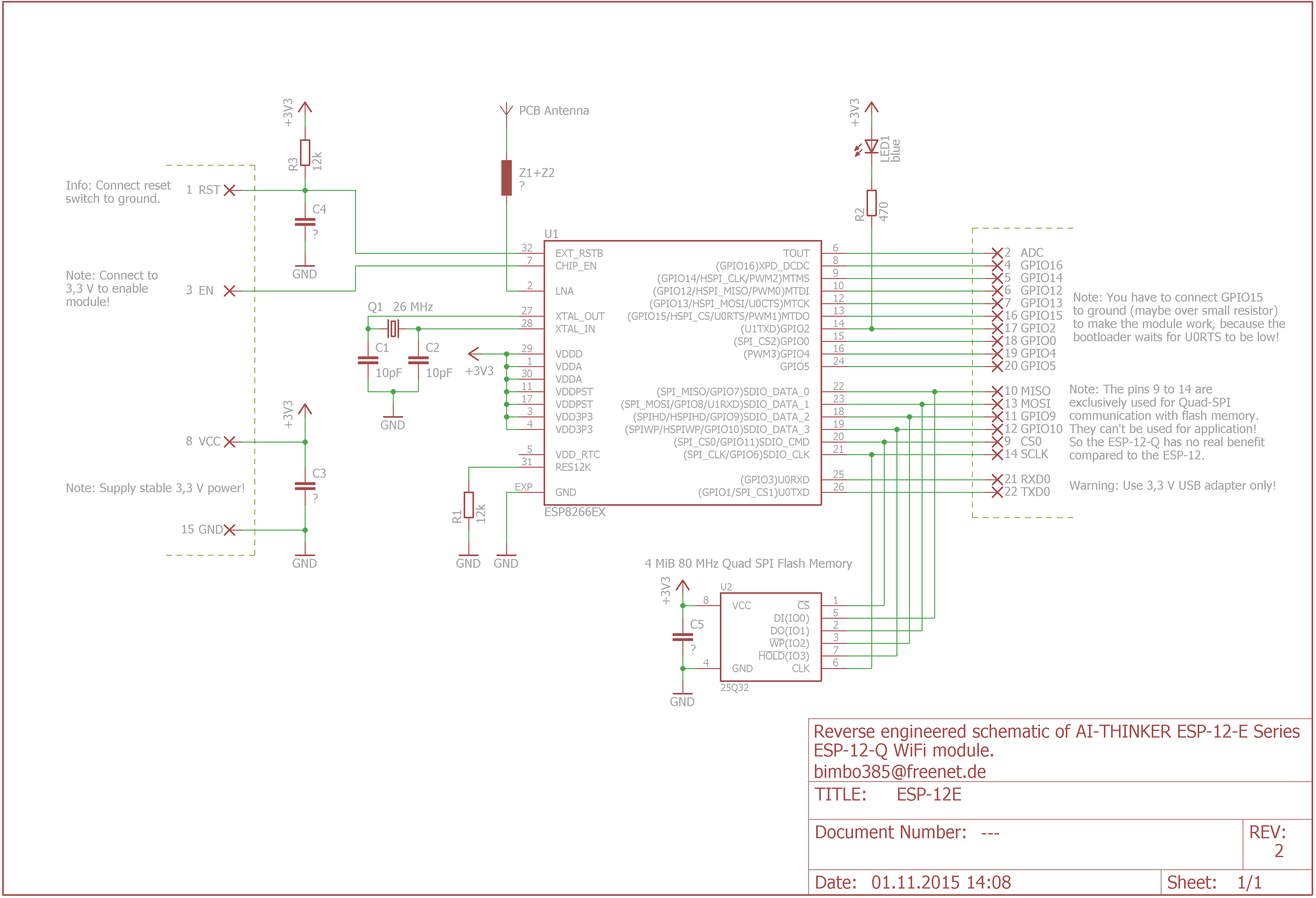

Using AT commands
Every command must end with a CR/LF sequence. On minicom, this can be obtained using CTRL-M followed by CTRL-J. The AT commands are fully described in Espressif manual "AT Instruction Set".
Reprogramming the ESP8266
The ESP8266 can be reprogrammed. To do so, you can either go the easy way using Arduino or the hard way installing a cross-compiler, a firmware uploading tool, etc.
Using the Arduino environment
(To be completed.)
Building and installing the cross-compiler and sdk
I have followed the indications given here. A lot of information is also provided by Espressif on their BBS). In particular, a lot of documents are available on this page.
On a fresh MINT installation, here are the commands I had to type to get a complete development environment:
 git clone --recursive https://github.com/pfalcon/esp-open-sdk.git
 cd esp-open-sdk/
 sudo apt-get install autoconf
 sudo apt-get install gperf
 sudo apt-get install texinfo
 sudo apt-get install libtool
 sudo apt-get install automake
 sudo apt-get install ncurses-dev
 sudo apt-get install g++
 sudo apt-get install expat
 make STANDALONE=y
A lot of very interesting/important information about programming the ESP8266 are given here.
Uploading the software to the chip
The chip can be placed in the flash programming mode by pulling down GPIO0 during reset (Note: on my board I need to keep GPIO0 low during all the flashing process).
A flash download tool is provided by Espressif here. Other tools:
I have tried to use Esptool on Ubuntu without success (impossible to connect to the ESP). I guess this problem is related to my RS232 adapter, but I am not sure... So I finally switched to Espressif's flasher: it works... more or less. I have managed to upload the firmware at 115200 (and even faster) but I had to do the process several times *** with power cycling in between *** before success.
Restoring the AT firmware
The AT firmware can be found [4] at Espressif.
Using NodeMcu
The NodeMcu firmware can be found [here https://github.com/nodemcu/nodemcu-firmware].
To download the firmware, do
wget https://github.com/nodemcu/nodemcu-firmware/raw/master/0.9.2/512k-flash/nodemcu_512k.bin
and then flash it to the module using
python esptool.py --port /dev/tty.usbserial-ABC123456 write_flash 0x000000 nodemcu_512k.bin
or using Espressif's flasher (that's what I did).
As of april 2016, you can build your own customized NodeMCU firmware using [5].
(Note: I used a custom version version of NodeMCU on the ESP-12e.)
Using Lua to communicate through Wifi
See WiFi module.
 wifi.sta.config("myssid", "password");
 wifi.sta.connect();
Uploading LUA scripts to the node
Use [ https://github.com/4refr0nt/luatool|luatools], [6] or [7].
To install the latter (nodemcu-uploader), type
pip install nodemcu-uploader
and to execute:
nodemcu-uploader
Another solution is to use [8], a fancy IDE for NodeMCU. It allows to edit Lua scripts on your desktop, updload and execute them on the ESP with mouse clicks (for those who like ).
In practice, the Lua script is uploaded as a file to the ESP. Once the file is uploaded, the Lua "dofile" commands executes the script. If the file name is "init.lua", it is automatically executed at startup.
Playing with GPIOs
First, notice that each GPIO can source 12mA (source):

GPIO are controlled by the "gpio" module. Configuring and setting a GPIO output is as simple as:
 gpio.mode(5,gpio.OUTPUT)
 gpio.write(5,gpio.HIGH)
Note that "5" here refers to the NodeMcu IO map. It is neither the id printed on the board nor the pin number. The mapping between this id and the ESP8266 GPIO line is given on the following picture ( source):

One can also drive (some) GPIOs in PWM mode:
 pwm.setup(1, 100, 512)
 pwm.start(1)
100 is the clock frequency (in Hz) and 512 is the duty cycle (0 to 1023).
Using MQTT
MQTT is a stripped down version of DDS. A typical configuration contains a broker, one or several clients which publish and subscribe to topics. There are several brokers available on the Internet, e.g., test.mosquitto.org.
The MQTT standard is available here. Other information can be found on the dedicated web site mqtt.org.
- Connecting a Raspberry and an ESP using MQTT. Mosquitto is used as the MQTT server. On the ESP, the client is esp_mqtt. On an Arduino, you may use Paho (which also supports Windows, Linux, and FreeRtos].
Setting up MQTT on the Raspberry Pi
Using Mosquitto
Just type:
sudo apt-get install mosquitto mosquitto-clients python-mosquitto
Then you can retrieve all topics from the mosquitto test broker:
mosquitto_sub -h test.mosquitto.org -t "#" –v
To use you own broker, type
mosquitto
Then you can publish your own data on the command line:
mosquitto_pub -h localhost -t "eric" -m "10"
and see (in another terminal) that it has been correctly handled by the broker:
mosquitto_sub -h localhost -t "#" -v
returns:
eric 10
You can also use the following page: http://test.mosquitto.org/gauge/ When you publish a new value of topic "temp/random", it is displayed on a graphical gauge.
Using Paho
Let's try to compile paho on the Raspberry:
 git clone https://git.eclipse.org/r/paho/org.eclipse.paho.mqtt.embedded-c
 cd org.eclipse.paho.mqtt.embedded-c/
 make
Well, it should work but it doesn't:
 mkdir -p build/output/samples
 mkdir -p build/output/test
 cc -o build/output/samples/pub0sub1 MQTTPacket/src/../samples/pub0sub1.c -lpaho-embed-mqtt3c -I MQTTPacket/src  -L build/output
 /tmp/ccV9SzgN.o: In function `main':
 pub0sub1.c:(.text+0x148): undefined reference to `transport_open'
 pub0sub1.c:(.text+0x1cc): undefined reference to `transport_sendPacketBuffer'
 pub0sub1.c:(.text+0x29c): undefined reference to `transport_sendPacketBuffer'
 pub0sub1.c:(.text+0x414): undefined reference to `transport_sendPacketBuffer'
 pub0sub1.c:(.text+0x458): undefined reference to `transport_sendPacketBuffer'
 pub0sub1.c:(.text+0x474): undefined reference to `transport_close'
 pub0sub1.c:(.text+0x4a8): undefined reference to `transport_getdata'
 collect2: ld returned 1 exit status
 Makefile:106: recipe for target 'build/output/samples/pub0sub1' failed
 make: *** [build/output/samples/pub0sub1] Error 1
The makefile is erroneous and must be corrected as follows (see here):
 ${SYNC_SAMPLES}: ${blddir}/samples/%: ${srcdir}/../samples/%.c ${srcdir}/../samples/transport.o
 	${CC} -o $@ $^ -l${MQTT_EMBED_LIB_C} ${FLAGS_EXE}
And now it compiles smoothly. To run the samples, the LD_LIBRARY_PATH shall include "<wherever>/org.eclipse.paho.mqtt.embedded-c/build/output".
With Python
I used paho-mqtt. To install:
sudo pip install paho-mqtt
The python code (taken from I-don't-remember-where) connect to IBM test server :
 host="messagesight.demos.ibm.com"
 port=1883

 def on_connect(pahoClient, obj, rc):
 # Once connected, publish message
 	print "Connected Code = %d"%(rc)
 	client.publish("eric/test", "Hello World", 0)


 def on_log(pahoClient, obj, level, string):
 	print string

 def on_publish(pahoClient, packet, mid):
 # Once published, disconnect
 	print "Published"
 	pahoClient.disconnect()

 def on_disconnect(pahoClient, obj, rc):
 	print "Disconnected"

 # Create a client instance
 client=paho.Client()

 # Register callbacks
 client.on_connect = on_connect
 client.on_log = on_log
 client.on_publish = on_publish
 client.on_disconnnect = on_disconnect

 #connect
 x = client.connect(host, port, 60)

 client.loop_forever()
Setting up the MQTT client on windows
I use [9]. It is nice but heavy...
Compiling and installing the MQTT client on the ESP8266
Using NodeMCU
In a first attempt, I used the NodeMCU firmware which comes with MQTT. Here is a typical script that publish and subcribes to the "/eric/test" topic. I use the mosquitto" test broker.
 wifi.sta.config("edvac","xxxxxxx")
 wifi.sta.connect()

 print(wifi.sta.getip())

 m = mqtt.Client("my_id", 120)

 m:on("message", function(conn,topic,data)
 	print(topic .. ":")
 	if data ~= nil then
 		print(data)
 	end
 end)

 m:connect("test.mosquitto.org",1883,0, function(conn)

 	m:subscribe("/eric/#",0,function(conn)
 		print("Subscription OK")
 	end)

 	m:publish("/eric/my_value", 1234,0,0,function(conn)
 		print("Topic published")
 	end)

 end)
The command dofile("script.lua") runs the script. If the connection succeeds, one should see the following display:
 Subscription OK
 Topic published
 /eric/my_value
 1234
The "complete" script used to control 4 relays is given hereafter.
STAMODE = {
STATION_IDLE             = 0,
STATION_CONNECTING       = 1,
STATION_WRONG_PASSWORD   = 2,
STATION_NO_AP_FOUND      = 3,
STATION_CONNECT_FAIL     = 4,
STATION_GOT_IP           = 5
}

-- Mapping relay id <=> GPIO output
map = { [0] = 0, [1] = 5, [2] = 6, [3] = 7 }

--
-- Generate a beep of freq <freq> and duration <duration>
--
function beep(freq, duration)
    pwm.setup(2,freq,100)
    pwm.start(2)
    tmr.delay(duration*1000)
    pwm.stop(2)
end


function blinkon(freq,duty)
    pwm.setup(1,freq,duty)
    pwm.start(1)
end

function blinkoff()
    pwm.stop(1)
end

--
--
--
function mqtt_setup()

    m = mqtt.Client("esp8266e-lights", 120)

    m:on("message", function(conn,topic,data)
        if data ~= nil then
            relay = map[tonumber(data)]
            cmd = string.match(topic, 'relay(%a%a%a?)')
            if cmd == "on" then
                gpio.write(relay, gpio.LOW)
            elseif cmd == "off" then
                gpio.write(relay, gpio.HIGH)
            end
        end
    end)

    --m:connect("test.mosquitto.org",1883,0, function(conn)
	-- Connection on my local laptop.
    m:connect("192.168.0.44",1883,0, function(conn)
        -- Signal station connection success
        beep(880,500)
        blinkon(1,20)

        -- Subscription
        m:subscribe("/eric/#",0,function(conn)
            print("Subscription OK")
        end)

        -- Publications
        --m:publish("/eric/test", 1234,0,0,function(conn)
            --print("Publication OK")
        --end)

    end)

 end

--
-- The "connect" function has been stolen from http://www.esp8266.com/viewtopic.php?f=24&t=1292
--
function connect(timeout)
   local time = tmr.now()
   wifi.sta.connect()

   -- Wait for IP address; check each 1000ms; timeout
   tmr.alarm(1, 1000, 1,
      function()
         if wifi.sta.status() == STAMODE.STATION_GOT_IP then
            tmr.stop(1)
            print("Station: connected! IP: " .. wifi.sta.getip())
            -- Signal station connection success
            beep(440,1000)
            blinkon(1,200)
            mqtt_setup()
         else
                     if tmr.now() - time > timeout then
                        tmr.stop(1)
                        print("Timeout!")
                        if wifi.sta.status() == STAMODE.STATION_IDLE          then print("Station: idling") end
                        if wifi.sta.status() == STAMODE.STATION_CONNECTING       then print("Station: connecting") end
                        if wifi.sta.status() == STAMODE.STATION_WRONG_PASSWORD    then print("Station: wrong password") end
                        if wifi.sta.status() == STAMODE.STATION_NO_AP_FOUND    then print("Station: AP not found") end
                        if wifi.sta.status() == STAMODE.STATION_CONNECT_FAIL    then print("Station: connection failed") end
                  end
         end
      end
   )
end

--
-- Initialize GPIO outputs, all inactive.
--
for _,v in pairs(map) do
    gpio.mode(v,gpio.OUTPUT)
    gpio.write(v,gpio.HIGH)
end

--
-- Setup communication and start
--
blinkon(1,512)

wifi.sta.config("edvac","xxxxxxx")
connect(10000000)
Using the bare ESP
See [10].
Other sources of information
- ESP8266 community wiki
- Basic
- [11]: LUA on the ESP¨8266. You can build your version of NodeMCU on the net using site: configuration is done on the web site page and they buld the appropriate version of the firmware.
- http://www.labradoc.com/i/follower/p/notes-esp8266