Quoi de neuf 2020
From Eric
(Difference between revisions)
m |
m |
||
| Line 5: | Line 5: | ||
* Playing with the [[CubeCell]] LoRa enabled module. | * Playing with the [[CubeCell]] LoRa enabled module. | ||
** I have bought two CubeCell modules from Heltec (see [https://heltec-automation-docs.readthedocs.io/en/latest/cubecell/index.html# here]). These modules are fitted with a LoRa module and have a very low quiescent power consumption. Here is a picture of such module (bought on AliExpress): [[File:cubecells.jpg|400px|thumb|none]] | ** I have bought two CubeCell modules from Heltec (see [https://heltec-automation-docs.readthedocs.io/en/latest/cubecell/index.html# here]). These modules are fitted with a LoRa module and have a very low quiescent power consumption. Here is a picture of such module (bought on AliExpress): [[File:cubecells.jpg|400px|thumb|none]] | ||
| - | ** Unfortunately, I have bought 433MHz modules (read the order carefully before pressing "buy"...) that don't match my 868MHz Dragino. So I have hooked a SemTech SX1278 433 Mhz module to an ESP32 to check if those CubeCell actually work. See some doc [https://1drv.ms/w/s!AuATPoIeeSgFlP4gQMVyuze-uzpfeg?e=mcqSVx here]. As of today I have: one CubeCell that sends messages via LoRa, a ESP32 | + | ** TRhose modules can be conected to a solar cell and a battery to ber fully autonomous. [[File:cubecells-solar.jpg|400px|thumb|none]] |
| + | ** Unfortunately, I have bought 433MHz modules (read the order carefully before pressing "buy"...) that don't match my 868MHz Dragino. So I have hooked a SemTech SX1278 433 Mhz module to an ESP32 to check if those CubeCell actually work. See some doc [https://1drv.ms/w/s!AuATPoIeeSgFlP4gQMVyuze-uzpfeg?e=mcqSVx here]. As of today I have: one CubeCell that sends messages via LoRa, a ESP32 Wroom that receives it and advertise them via BLE serial... | ||
== November 2020 == | == November 2020 == | ||
Revision as of 21:19, 22 December 2020
Experiments carried out in the past (from 2011) are described hereafter: 2019, 2018, 2017, 2016, 2015, 2014, 2013, 2012, 2011
Contents |
December 2020
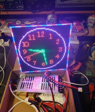
- Playing with the HD-W60-75 led matrix driver module.
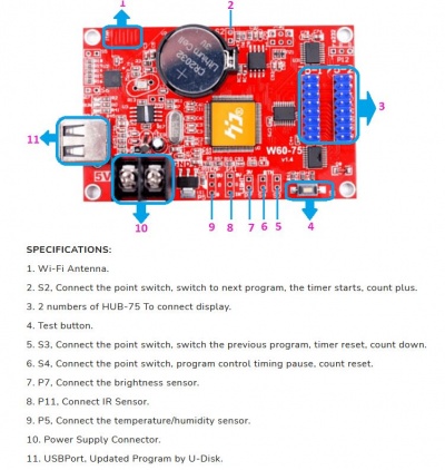

- I have bought a few led matrices (HUB12, 16x32 pixels, and HUB75, 64x64 at P3 and 64x128 at P2). Thos matrices can be driven via W60 modules with allows animations to be loaded on a USB stick or hd-be transmitted via Wifi. Animations are built using the HD2016 (or 18 or 20) software (password is 168). Pretty neat (at basically useless...)
- I have bought a few led matrices (HUB12, 16x32 pixels, and HUB75, 64x64 at P3 and 64x128 at P2). Thos matrices can be driven via W60 modules with allows animations to be loaded on a USB stick or hd-be transmitted via Wifi. Animations are built using the HD2016 (or 18 or 20) software (password is 168). Pretty neat (at basically useless...)
- Playing with the CubeCell LoRa enabled module.
- I have bought two CubeCell modules from Heltec (see here). These modules are fitted with a LoRa module and have a very low quiescent power consumption. Here is a picture of such module (bought on AliExpress):
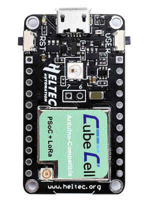
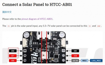
- TRhose modules can be conected to a solar cell and a battery to ber fully autonomous.
- Unfortunately, I have bought 433MHz modules (read the order carefully before pressing "buy"...) that don't match my 868MHz Dragino. So I have hooked a SemTech SX1278 433 Mhz module to an ESP32 to check if those CubeCell actually work. See some doc here. As of today I have: one CubeCell that sends messages via LoRa, a ESP32 Wroom that receives it and advertise them via BLE serial...
- I have bought two CubeCell modules from Heltec (see here). These modules are fitted with a LoRa module and have a very low quiescent power consumption. Here is a picture of such module (bought on AliExpress):


November 2020
Playing with the Colorlight 5a-75b FPGA board. This very cleap FPGA board is used to control LED matrix panels. It is fitted for a Lattice ECP5 FPGA, a 32Mbits SPI flash, a 2MB 200MH SRDAM, and 2 Gigabits ethernet PHYs. The Lattice cheap is supported by a bunch of free development tools (synthesis, placement, bitstream generation).
See Chubby75 on the V8 version. This board can be bought on AliExpress for $12 or so. Here is a picture of the board:

August 2020
- Not much... I am trying to build a "Pulse counting FM demodulator". I use the circuit described (and expained) in (yet another) video from the excellent w2aew. The circuit is very simple: .
- Unfortunately, even tough I use the same components as w2aew, the behaviour of the circuit is not satisfying.
- So I have created a LTSPICE simulation to see if the simulation and the actual circuit behave in the same way. The analysis is given in this document.
July 2020
- I have bought (and played with) a bunch of RF components. See RF equipment.
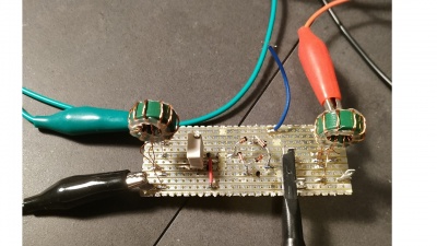
- I am currently building a diode ring mixer. See the video about diode ring mixers by the excellent w2aew (check all videos, they are all great!). See also the one by Charlie Morris.
- Here is my homebrewed diode mixer:
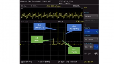
- A few pictures showing the spectrum of the signal obtained by mixing a 2MHz and a 7MHz signal.
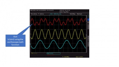
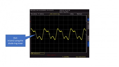
- And the mixed signal computed by the oscilloscope and mixed by the diode mixer:
- Here is my homebrewed diode mixer:
- I have watched the complete course about Python for IA by Machine Learnia (in french). Excellent!


June 2020
- Nothing.
May 2020
- May 3rd
- I have created a URDF model of the robot. This allows the automatic generation of the transformations (ROS' TF).
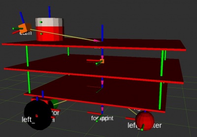
- The source files are here.
- The model is not aimed at being realistic: it only carries all the geometrical transformations between links (using joints).
- By the way, I try to describe what I do (more or less) in this document.
- I have created a URDF model of the robot. This allows the automatic generation of the transformations (ROS' TF).
- May 1st
- Still locked at home...
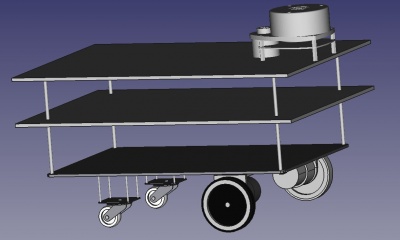
- I am curently creating a simple URDF model of my robot in order to generate transformations (from base link to the LIDAR, to the camera, etc.) automatically.
- So I have first modelled it (partially) with FreeCad:


April 2020
- April 18th
- I used to think that my Ender 5 was printing correctly... but no! By playing on the filament flow, I was able to prevent the head bumping on the printed surface. But the problem was NOT over-extrusion! The actual problem comes from the fact that there are two versions of the Ender5, with two different z-screw: one with 400 steps per cm and the other with 800 steps per cm. I own the second one but the default Marlin firmware for the Ender comes with the 400 steps / cm configuration (see file "Configuration.h", parameter "DEFAULT_AXIS_STEPS_PER_UNIT").
- So there were two solutions: either recompiling the firmware with the appropriate step per unit configuration, or using the "M92 Z800" directive.
- For the moment, I have simply changed the start G-code in Cura (Preferences/printers/Machine settings) and added "M92 Z800". Now, it seems that I am a bit underextruding. I have printed the calibration cube (here ) and the faces are far too thin with the current 75% flow.
- April 17th and before
- I am currently playing with Vue.js. My objective is to develop a small control interface for my robot. I have to say that building an HMI using Javascript and all the Web technologies is much much more efficient (in terms of development time) than using classical technologies! In a few hours (starting from a close-to-zero knowledge about Web techs), I have been able to create a small interface that displays the orientation of the robot in 3D (using three.js), plots some of its parameters (using Google Charts,) etc.
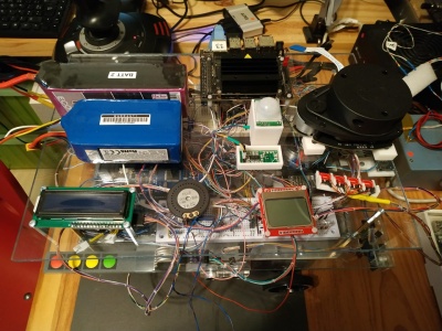
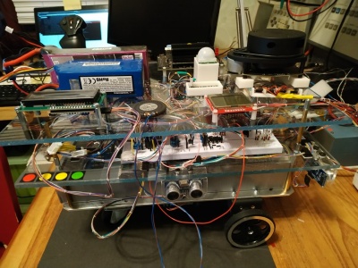
- UsineAGazBot,my robot has done its first steps!
- It is fitted with... 2 arduino pro mini, one arduino due, one arduino mega, one ESP32, one Raspberry Pi, one FPGA (Tang Nano), and one Jeston nano!, all these guys being connected via a CAN network.
- Surely, it is overkill, but I wanted to add functions one y one, incrementally, each of them beig hosted by its own CPU. Later, I'll try to make them fit in slightly less silicium.
- For the moment, it is completely remotely operated, but it is built using ROS and there shouln't be that many difficulties to make it autonomous.
- Here are a few pictures of the beast (I admit that it is difficult to find where's the front, where's the bottom...):
- I have finally managed to make my Ender 5 work: it was simply overextruding. By reducing the extrusion speed by 20%, it works just fine. I certainly have to calibrate the mm/step but, as it works... By the way, as my bed is not level, I use babystepping to ensure that the first layer sticks to the bed. This is manual, but not that complicated.


Mars 2020
- Covid 19 quarantine
- I have updated by Ender 5 3D printer with the latest version of Marlin. I have basically followed the indicated given by TeachingTech, here. I have had some difficulties when updating the firmware using the Arduino ISP. The trick was (i) to use a high quality USB cable, (ii) to place a 100uF capacitor between the reset pin and the ground on the Arduino. Once done, there was no problem to install the bootloader. Then I used the modified Marling configuration files proposed by TeachingTech. In order to add manual mesh leveling, I have uncommented the following #defines: MESH_BED_LEVELING, RESTORE_LEVELING_AFTER_G28 and LCD_BED_LEVELING in Configuration.h. Then I have commented ARC_SUPPORT (Configuration_adv.h) otherwise the binary was too big. And that's it.