Quoi de neuf 2018
From Eric
Experiments carried out in the past (from 2011) are described hereafter:
Contents |
December 2018
- I have spent a few days playing again with Vivado, now on a Arty z7 board
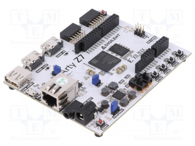

- My objective was to play with the AXI4 lite and full from the Zynq's PL side. I also wanted to access DDR from the PL.
- The objective reached: I drive some LEDs connected to an AXI GPIO IP and write data into DDR from some very simple pieces of Verilog. Well, Vivado makes access to AXI4 buses pretty easy... You can find some notes here.
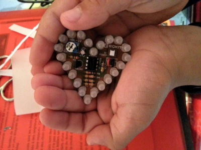
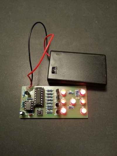
- Two kits bought on eBay for my son to learn soldering: a "breathing" heart and a dice


November 2018
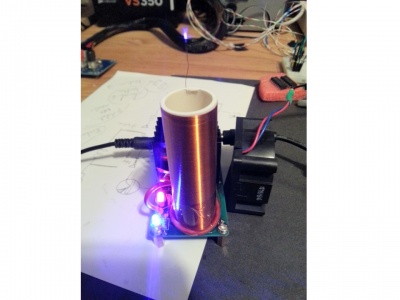
- Soldered a "mini tesla coil speaker" (found for 4€ on eBay. It works pretty well. (To make it work, wind the primary in the correct direction and place the loop at the lower end of the secondary coil)
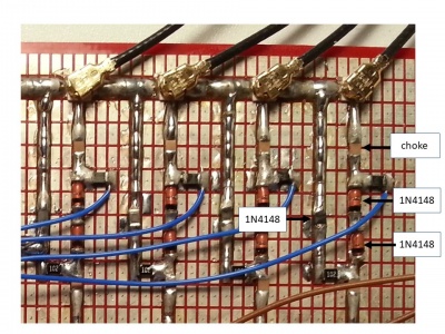
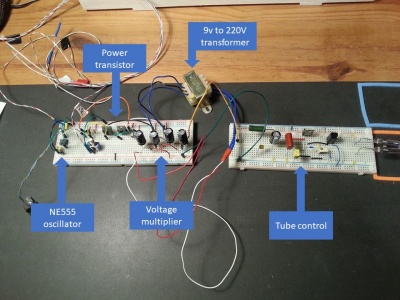
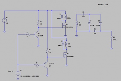
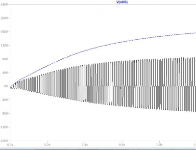
- Completed my stroboscope with my own high voltage power supply. Here is a picture of the whole system . Here is a schematic of the power supply and a curve of the voltage output


October 2018
- October 20th
- Built a stroboscope with a flash tube. Well... the HV part has been bought on eBay. I'll do my own when I find a 9V=>220V transformer.


- I have used by reflow soldering equipment (see below) to reproduce the BeagleLogic logic analyzer. The result is not that much convincing for a small board with one main component: the overall soldering process took more time than with my hot air gun and I have had severral soldering bridges. This technique is certainly good for boards with many components...
- October 13th
- Some bibliographical work about stroboscope (in French), here.
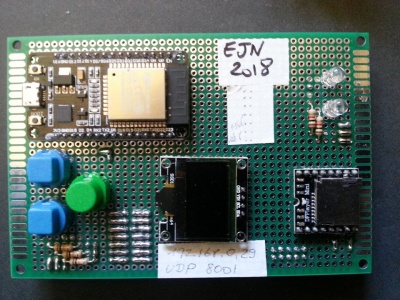
- Built a a small board with a DWM1001 sensor and a ESP32:


September 2018
- Nothing
August 2018
- I have bought a few equipments to do "reflow soldering" of SMT components:
- an oven controller (from Beta-layout, here):

- an oven (Severin TO 2034), the one that is sold by Beta-layout in one of their kits:

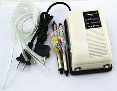
- a modified aquarium pump to pick and place SMT components (bought on eBay):
- a pneumatic solder dispenser (YDL-983A):

- an oven controller (from Beta-layout, here):
- This is clearly not an high-tech equipment, but it should do the job for me. At the beginning of my seach, I planned to buy the low-cost T962 reflow oven. However, it needs to be modified in a significant manner to make it work correctly, so I chose another solution: use a standard oven with an external controller. This solution is presented by Dave in his EEVBlog.
- For the moment, I have only calibrated the controller. I'll use the oven to reproduce the Beaglebone logic analyzer I once built (see below).
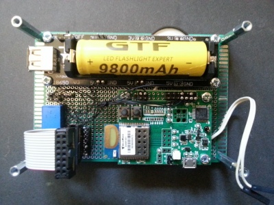
- I am playing with my ESP32 board.
- I have hooked a DFplayer, a DWM1001 localization sensor, a few leds and buttons, to the chip.
- I have experienced some difficulties because many of the ESP32 I/O pins are used either by the SPI Flash or the I2C OLED display, or simply as configuration means for the ESP32 ("strapping pins"):
- Straping pins: GPIO12 (MDTI), GPIO0, GPIO2, GPIO15 (MDTO). For instance, GPIO2 is used to select the flash voltage (3.3 or 1.8, note that this sensing can be inhibited by setting the flash voltage to either 3.3V (0) or 1.8V (1) using the fuse.). The strapping pins are described in section 2.3 ("strapping pins") of the [https://www.espressif.com/sites/default/files/documentation/esp32_datasheet_en.pdf WROOM datasheet).
- Pins 4 and 5 are used by the OLED display
- Pins TX and RX are used for debugging
- GPIOs 6, 7, 8, 9, 10, 11 are used by the external flash memory on ESP-WROOM32. See schematic below:
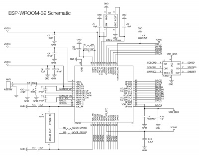
- The software (draft, PlatformIO src directory) can be found here. It might be useful if you want to use UART (acccess to a dfplayer), GPIOs (leds and buttons), SPI (access to DWM1001), I2C (access to SSD1366 OLED display), Wifi, and UDP client:server. The code is basically a mixture or multiple sources (I don't remember which...).


July 2018
- Played with my brand new galvo (from China).


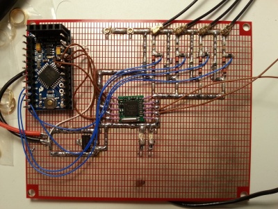
- Each galvo must be driven by a -15 to 15V differential signal. I have use an arduino pro mini, two DACs, and two op amps to create those signals. And it works...

- Here is a snapshot of the differential signal (for a sinusoid):

- And the addition of those two signals:

- The laser is driven by a constant current source based on a LM317:

- More information can be found at [1]. I have bought my galvos on eBay, here.
- For the moment, the result is not that spectacular (a moving ellipse). I have to write some code to draw lines and other things...
June 2018
- I have built a small logic analyzer based on a BeagleBone Black. Well, the hardware and software of the BeagleLogic have been designed by Kumer Abhishek (he is currently designing a standalone version of the BeagleLogic). This logic analyzer uses the two real-time processors (PRU) of the BeagleBone's Sitara SoC to ensure a precise sampling. Some details about the BeagleLogic board are given on a dedicated page.
- My only effort was to order the PCB to jlcpcb (very cheap) and to solder the tiny 74LVCH16T245 used as a level adapter (to be able to sample 5V signals)... I have had some problems with solder bridges on the first board, so I used a thinner needle (23GA) to put the solder paste on the second board.
- Here are pictures of the thing: and a close view of the adapter cape:
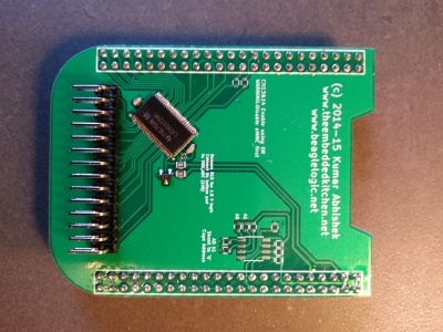
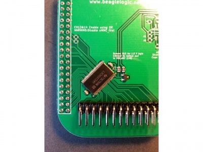
- Well, note that since I have soldered the connectors on the wrong side of the board (yes, I have...), I had to use a bunch of Dupont cables to connect the "cape" to the board. I have ordered a new 74LVCH16T245 to make another, correct, version of the board.
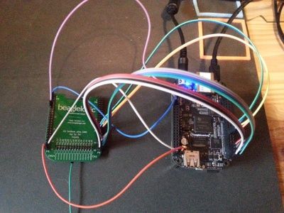
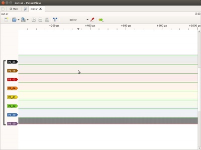
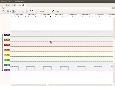
- The data sampled by the BeagleLogic can be displayed using Sigrok's PulseVision:
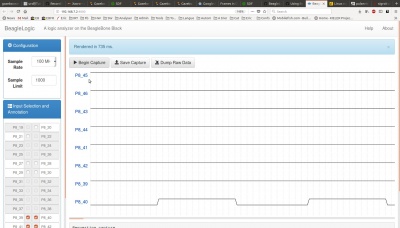
- The sampling itself can be done using the CLI version of Sigrok running on the BeagleBone. Kumer has also developed a simple Web interface:
- Could be a nice project for my Z-turn ZYNQ board...


- Playing with my small robot arm.
- I have modeled it using FreeCAD (see model and actual system below; the gripping arm is still to be modeled).
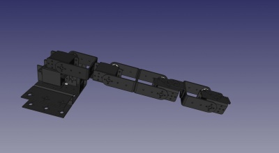 The objective is to drive it using inverse kinematics. To do that, I need to calculate all the distances between axes, which will be easy from the 3D model. Furthermore, this 3D model will be useful to create a simulated dynamic model of the arm using, for instance, Gazebo or ROS. Now, I am strugling with the URDF file. More to come...
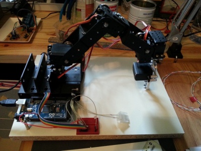
- I have modeled it using FreeCAD (see model and actual system below; the gripping arm is still to be modeled).


May 2018
- Un bonjour amical à François et Jacky. Mon dieu (enfin, celui des autres), le temps passe...
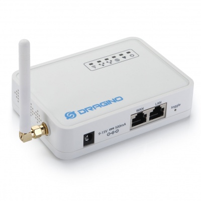
- I have received my Dragino LoRa gateway. (See my notes.) Now I am able to send data from an Arduino (equiped with a Semtech LoRa transceiver) to a MTQQ broker (ThingsSpeak). Now, I have to build one or two measurement devices (to measure what?...). The challenge is to keep the energy demand as low as possible so that batteries do not need to be refilled too often. One possibility is to use a standard Arduino that will spend most of its time in deep sleep mode and be awaken every 15 or so seconds by a RTC. Another solution could be to use a very low energy msp430. To be continued...
- I have tried the Gogle Assistant SDK (tutorial here). My objective is to be able to switch lights on / off using Googl's vocal interface. Not very useful actually...
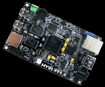
- (Still) playing with my Zturn Zynq board. I have managed to install Petalinux (on core 0) aside FreeRTOS (on core 1). See notes.

April 2018
- Experiment Micropython on ESP32. See notes.
- Playing with my Zturn Zynq board. See notes. .
- Experiment the Ti MSP340 Chronos watch.

March 2018
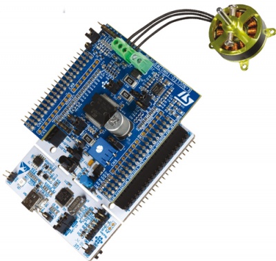
- First experiments with the STM32 Nucleo (NUCLEO-F302R8) and motor control extension board (X-NUCLEO-IHM07M1), the STM32 Nucleo pack FOC and 6-step motor control: I am still fighting with the motor SDK... I am writing a note that will eventually explain in a how to setup the environment in a unique document ...

February 2018
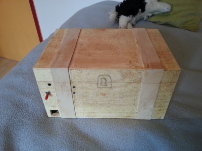
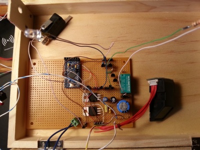
- Built a safety case for my son, using a fingerprint sensor. Here are a few pictures:
 The code is here.
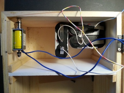


January 2018
- Playing with the ESP8266 using the Espressif SDK. (Search for ESP8266 for other experiments using NodeMCU). I am using the PlatformIO environment. I am now able to print a message on the tiny screen from my laptop, through internet:
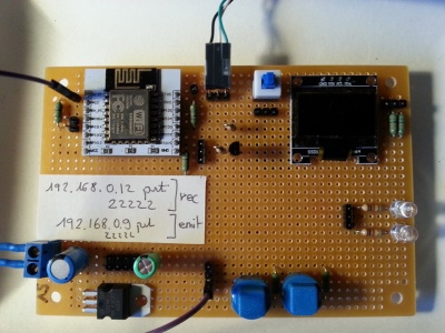
- Trying to build a doppler-based "fox hunter" (on-going). See notes here