Quoi de neuf 2016
From Eric
Experiments carried out in the past (from 2011) are described hereafter:
Contents |
December 2016
- [29/12/2016]
- Yes!I have managed to use Erika Enterprise on my TriCore. Here is a stupid video: 4 blinking leds. One for core 1, two for core 2, and another one for core 3. Details are given in my memo. (EDITED 098/07/2017: things seem to have changed... I have experienced problem compiling with the latest HITECH compiler: the ".d" files are malformed. The simplest (but stupid) solution consists to simply delete these files.
- [25/12/2016]
- My project ("Ingequip") is now completed. During the last months, most of my time and energy have been spend on it, hence the long list of "Nothing" in this journal.
- Anyway, I have bought a nice arduino-like board with a TriCore microcontroller from Infineon:
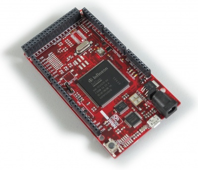

- It is called a "Shieldbuddy" and it is sold by Hitex (here). You can use it just as any other Arduino, except that the beast runs much faster than most of the other Arduinos (200Mhz) and hosts 3 32-bit cores! You can find more information in a DesignSpark article, much more information in the documentation provided by Hitex (see their blog) and, of course, much much more information at Infineon.
- By the way, note that this microcontroler comes which a bunch of peripheral devices including a CAN controler, a GTM (yesssss!),... You can program it with the Arduino Processing environment (i.e., the board is supported) or using Eclipse. In the latter case, you have to download Infineon framework which comes with a library of low-level services. Additionnaly, I give a few details on how to use this board in a dedicated memo.

November 2016
- Nothing
October 2016
- Nothing.
September 2016
- Nothing.
August 2016
- [20/8/2016]
- I have connected a viewfinder extracted from an old camcorder to an old composite camera:(video here).
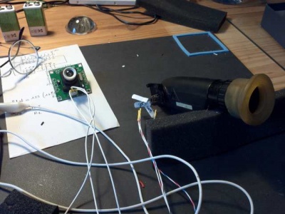
- I have also dismantled an old house ring fitted with a camera and a flat black-and-white screen.
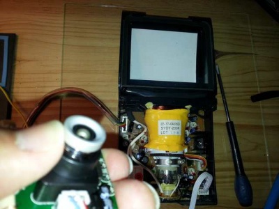
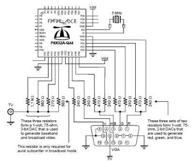
- I have connected both the viewfinder and the flat screen on my Propeller board: the Propeller comes with a driver that makes composite video a piece of cake, i.e., a matter of adding three resistors to build a primitive DAC, as shown below: . The result is correct on the viewfinder and bad on the flat screen.
- I have connected a viewfinder extracted from an old camcorder to an old composite camera:
- [13/8/2016]
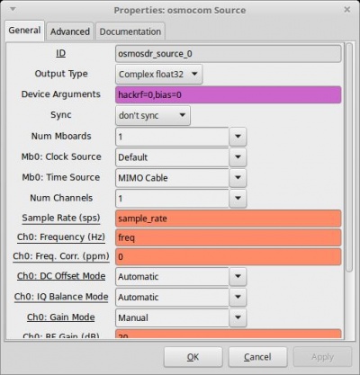
- I have received my HackRf one. I have started plying with it with a mitigated success: even when the LNA is added, I only receive the FM bands (with the ANT500 antenna). Well, I live on the countryside, in a "valley"... so it probably explains the lack of results. I have found how to activate the phantom power supply (for the LNA) in GnuRadio. Look at the pink area in the followin g picture: set the "bias" parameter to 1 to activate the phantom power supply.
- I have completed the hardware of my vacuum cleaner robot: the Raspberry Pi 2 and its camera, the Atmega-based board with its H-bridges, the CAN controller boards and the level converters, the audio amplifier are now in place:
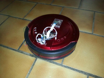
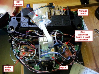
- I have implemented a small audio amplifier with a TDA 2030:
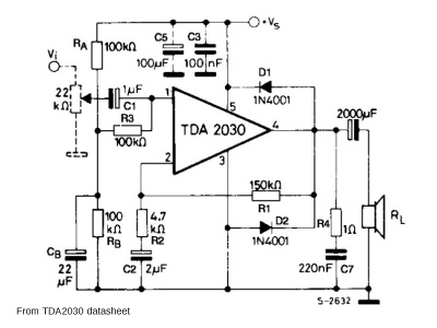 . Thanks to "espeak", the robot can now speak...
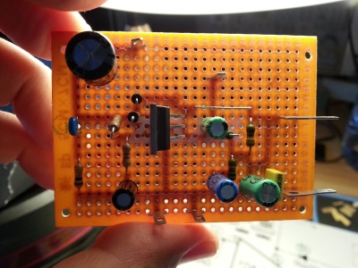
- Here is a short video of its first (autonomous) steps.
- I have received my HackRf one. I have started plying with it with a mitigated success: even when the LNA is added, I only receive the FM bands (with the ANT500 antenna). Well, I live on the countryside, in a "valley"... so it probably explains the lack of results. I have found how to activate the phantom power supply (for the LNA) in GnuRadio. Look at the pink area in the followin g picture: set the "bias" parameter to 1 to activate the phantom power supply.


July 2016
- [15/7/2016]
- I have ordered a Hack-RF one, a ANT-500 telescopic antenna, a "Ham It Up" upconverter (all from NooElec) and a LNA preamp (https://www.passion-radio.com from [Passion Radio)]. I have started studying IQ modulation and demodulation. Nice videos on SDR are proposed by the Hack Rf designer, Michael Ossmann. You can find them at http://greatscottgadgets.com/sdr. As usual with w2aew, very interesting videos on IQ modulation here (#170) and here (#171).
- [14/7/2016]
- My recycled vacuum cleaner robot:
- I have implemented the HMC5883 driver (compas) on I2C.
- I have connected my RPi to the robot's control computer via CAN. Here is a picture of the current setup.
- My recycled vacuum cleaner robot:
June 2016
- [26/06/2016]
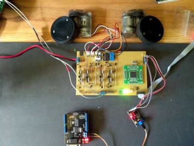
- I have completed the MCP2515 driver for the Atmega128 board. Currently, I can drive the motors and get the odometry from an Arduino Uno fitted with a CAN interface. Next phase: connect the ATmega128 board with my Raspberry (for which I have already written a userland MCP2515 driver, see december 2015):
- I have completed the MCP2515 driver for the Atmega128 board. Currently, I can drive the motors and get the odometry from an Arduino Uno fitted with a CAN interface. Next phase: connect the ATmega128 board with my Raspberry (for which I have already written a userland MCP2515 driver, see december 2015):
- [12/06/2016]
- I have built a control board for my ex vacuum-cleaner robot. It currently integrates an Atmega 128A, two H-bridges (with direction/drive signals), a LM324 comparator (with-hysteresis) to acquire the odometry sensors. Next step is to add a CAN bus so that I can connect the board to a Raspberry (see earlier posts).
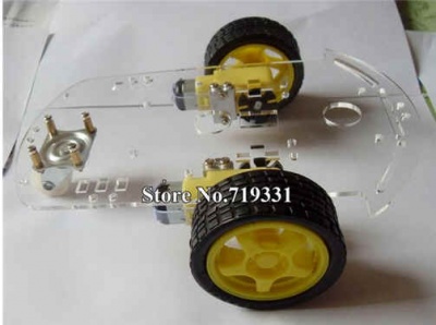
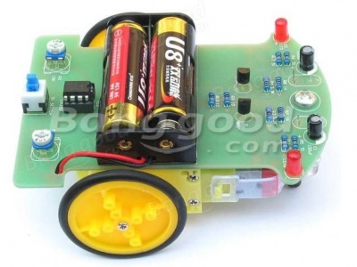
- I have built a small light-following robot for my son (yet another LM324, two LDR, two 2N2222 and that's it). The robotic platform comes from Banggood:


May 2016
- [29/5/2016]
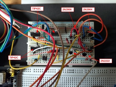
- I have managed to drive the motor and get the odometry signal of my ex-vacuum cleaner. I have built a H-bridge using two TIP41 (NPN) and two TIP42 (PNP), two 2N2222 to drive the power transistors. In order to prevent short-circuits in case of a bad command, I have added a pair of 2N3904/3906 to replace the raw (motor CW power, motor CCW power) commands by a (motor command, direction). Here are a few pictures
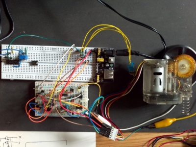
- To test the H-bridge, I have used a 555 as a PWM generator. Here is the circuit:
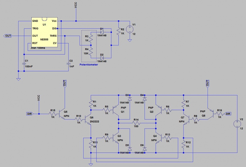
- The motors are fitted with an IR led and a facing optical sensor. I use an LM324 op amp as a comparator in order to get nice, steep rising, and falling edges.
- I have managed to drive the motor and get the odometry signal of my ex-vacuum cleaner. I have built a H-bridge using two TIP41 (NPN) and two TIP42 (PNP), two 2N2222 to drive the power transistors. In order to prevent short-circuits in case of a bad command, I have added a pair of 2N3904/3906 to replace the raw (motor CW power, motor CCW power) commands by a (motor command, direction). Here are a few pictures
- [23/5/2016]
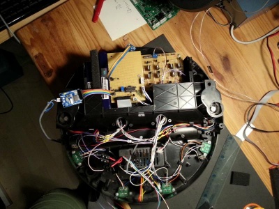
- For 5€, I have found a used vacuum cleaner robot on a "garage sale", an entry-level Yonis cleaner y-1000 (with a dead battery). I have dismantled the robot and I have removed whatever I have considered useless. Now I have to make the various motors and sensors work before considering adding: several ultrasonic sensors (or one sensor on a servo or stepper motor), a compass, etc.
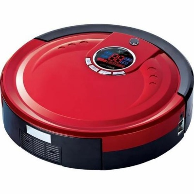
- For 5€, I have found a used vacuum cleaner robot on a "garage sale", an entry-level Yonis cleaner y-1000 (with a dead battery). I have dismantled the robot and I have removed whatever I have considered useless. Now I have to make the various motors and sensors work before considering adding: several ultrasonic sensors (or one sensor on a servo or stepper motor), a compass, etc.
- [8/5/2016]
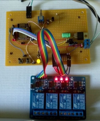
- I have completed my ESP8266 board: now, I can control 4 relays from my phone... I use : a MQTT broker running on my laptop (it could run on my RPi as well), a MQTT client running on the ESP (using NodeMCU), a MQTT client running on my phone. The small LUA script running on the ESP subscribes to the relay control message and switch the GPIOs accordingly. I have added a small buzzer for the fun. Here is a small demonstration video. For detail, please refer to the ESP8266 page.
- I have assembled a small line-following robot kit (sold by Banggood for around 5€). My son lend me a hand to solder the components. It works pretty well: a very nice present for a child. Here is a picture of the thing:. A short video showing the robot can be found here
- [6/5/2016]
- From the ESP-01 to the ESP-12... The ESP-12 version of the ESP8266 board provides much more IOs than the ESP-01. The ESP-12 alone (i.e., without any microcontroller aside) can manage both the WiFi communications *** and *** the physical inputs and outputs. Fortunately, I had two pieces of this ESP-12e at hand...
- I have updated the ESP8266 page accordingly. Note that on the ESP-12e, GPIO15 must be tied to GND !!! (By the way, don't forget to use a resistor to pull the pin down, just in case...)
- From the ESP-01 to the ESP-12... The ESP-12 version of the ESP8266 board provides much more IOs than the ESP-01. The ESP-12 alone (i.e., without any microcontroller aside) can manage both the WiFi communications *** and *** the physical inputs and outputs. Fortunately, I had two pieces of this ESP-12e at hand...
- [1/5/2016]
- I have continued my experiments with the ESP8266. I have played a little bit with the MQTT protocol and the ESP (see the ESP page). MQTT is a nice and simple publish/subscribe protocol; a kind of very light DDS. Now, I can publish a "topic" on my ESP and subscribe to the same topic on my Raspberry (which also serves as a MQTT broker). For the moment, I use the NodeMCU ESP firmware which provides a Lua interpreter on the ESP. With this configuration, everything works out of the box and establishing a connection to the MQTT broker though a WiFi connection is a piece of cake. Here is a short video showing 4 relays being switched on/off via my mobile.
- The next step will be to use the Xtensa C cross-compiler to build the application from C code. This is for the fun because I think that there is sufficient room on the NodeMcu to implement the kind of IoT-application in Lua...
- I have bought a nice 320x140 LCD display for the Raspberry (around 12€ at Banggood). Hopefully, I found all the necessary explanations on the web to set it up.


April 2016
- [16/04/2016] First experiment with the ESP8266. First step was to connect the chip to my PC and use the AT commands. It works pretty well as long as you use an appropriate power supply: WiFi requires quite a lot of current; the first power supply is used was too weak.
- There is quite a lot of information about the ESP8266 available on the net. I have capture the most interesting parts (as of today) on the dedicated ESP8266 page.
- Slight improvement of the ADAU1701 board. Some details are given here. A short (and useless) video is available here.
March 2016
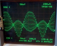
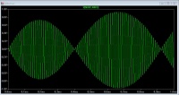
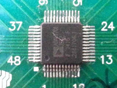
- Yes! I have managed to solder my 0.5 pitch ADAU1701 using my brand new hot-air soldering station. The result is pretty good even though I had to remove a few solder bridges. Here it is:
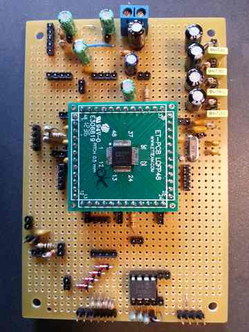
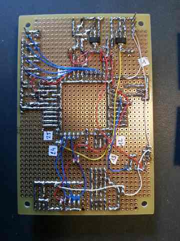
- I have also completed the board that hosts the ADAU1701 DSP and... it works pretty well. Here is a picture of the DSP generating sinusoidal and triangular waveforms:


- Here is the board (a slightly simplified version of Elektor's design or a slightly more complex design of AD's datasheet):
- You will (soon) find a few information on the ADU1701 in a dedicated page.


February 2016
- I have bought a cheap frequency generator (Feeltech FY3200S) and a hot-air soldering station (Aoyue int 852):


- I have managed to solder a 0.8 TQFP64 chip (an Atmega 128) using hot air. The result is pretty nice event though I had to remove 4 bridges. This success came after a first trial (with the same type of chip) which ended badly: one dead Atmega and a lost TQFP adapter.
- The key to success was:
- to solder at 350°C (I guess that this is slightly higher than actually necessary)
- to place the chip on the board, stick it with some Kapton tape, and then
- to put as little as possible soldering paste. (I think that putting the paste once the chip is in place prevents it migrating behing the pins where it could create short circuits. Well, it could possibly be removed afterwards using alcohol or aceton...)
- to use a medium nozzle (i.e., not the smallest)
- to remove the remaining bridges between pins using some desoldering wick and a large soldering tip (and not my Hakko-clone with its tiny tip).
- Here is the result: not too bad... This was a test run before I receive my tiny ADAU1701 (with a 0.5 pitch).

It took me more time than when I use my soldering iron but the result is nicer.
January 2016
- After watching this very interesting video about the Gilbert cell, I have built the following mixer (the schematics comes from the video)
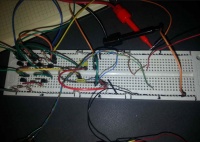
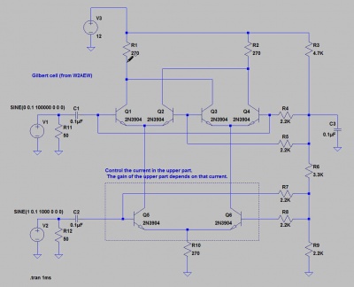
- As I have used non matched transistors, the mixing is not as symetric as it should be !