Quoi de neuf 2020
From Eric
(Difference between revisions)
m (→November 2020) |
m |
||
| (17 intermediate revisions not shown) | |||
| Line 1: | Line 1: | ||
Experiments carried out in the past (from 2011) are described hereafter: [[Quoi de neuf 2019 | 2019]], [[Quoi de neuf 2018 | 2018]], [[Quoi de neuf 2017 | 2017]], [[Quoi de neuf 2016 | 2016]], [[Quoi de neuf 2015 | 2015]],[[Quoi de neuf 2014 | 2014]], [[Quoi de neuf 2013 | 2013]], [[Quoi de neuf 2012 | 2012]], [[Quoi de neuf 2011 | 2011]] | Experiments carried out in the past (from 2011) are described hereafter: [[Quoi de neuf 2019 | 2019]], [[Quoi de neuf 2018 | 2018]], [[Quoi de neuf 2017 | 2017]], [[Quoi de neuf 2016 | 2016]], [[Quoi de neuf 2015 | 2015]],[[Quoi de neuf 2014 | 2014]], [[Quoi de neuf 2013 | 2013]], [[Quoi de neuf 2012 | 2012]], [[Quoi de neuf 2011 | 2011]] | ||
| + | == December 2020 == | ||
| + | * Trying to drive an oscilloscope cathode ray tube. See dedicated article [[oscilloscope]]. | ||
| + | * Playing with the HD-W60-75 led matrix driver module. [[File:HD-W60-75.jpg|400px|thumb|none]] | ||
| + | ** I have bought a few led matrices (HUB12, 16x32 pixels, and HUB75, 64x64 at P3 and 64x128 at P2). HD-W60 modules allows animations to be loaded from a USB stick or be transmitted via Wifi. Animations are designed using the HD2016 (or 18 or 20) software (password is 168) or the "LedArt" phone application. Pretty neat (but completely useless...)[[File:HD-W60-75-clock.jpg|400px|thumb|none]] | ||
| + | * Playing with the [[CubeCell]] LoRa enabled module. | ||
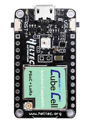
| + | ** I have bought two CubeCell modules from Heltec (see [https://heltec-automation-docs.readthedocs.io/en/latest/cubecell/index.html# here]). These modules are fitted with a LoRa module and have a very low quiescent power consumption. Here is a picture of such module (bought on AliExpress): [[File:cubecells.jpg|400px|thumb|none]] | ||
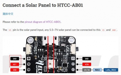
| + | ** TRhose modules can be conected to a solar cell and a battery to ber fully autonomous. [[File:cubecells-solar.jpg|400px|thumb|none]] | ||
| + | ** Unfortunately, I have bought 433MHz modules (read the order carefully before pressing "buy"...) that don't match my 868MHz Dragino. So I have hooked a SemTech SX1278 433 Mhz module to an ESP32 to check if those CubeCell actually work. See some doc [https://1drv.ms/w/s!AuATPoIeeSgFlP4gQMVyuze-uzpfeg?e=mcqSVx here]. As of today I have: one CubeCell that sends messages via LoRa, a ESP32 Wroom that receives it and advertise them via BLE serial... | ||
| + | |||
== November 2020 == | == November 2020 == | ||
Playing with the Colorlight 5a-75b FPGA board. This very cleap FPGA board is used to control LED matrix panels. It is fitted for a Lattice ECP5 FPGA, a 32Mbits SPI flash, a 2MB 200MH SRDAM, and 2 Gigabits ethernet PHYs. The Lattice cheap is supported by a bunch of free development tools (synthesis, placement, bitstream generation). | Playing with the Colorlight 5a-75b FPGA board. This very cleap FPGA board is used to control LED matrix panels. It is fitted for a Lattice ECP5 FPGA, a 32Mbits SPI flash, a 2MB 200MH SRDAM, and 2 Gigabits ethernet PHYs. The Lattice cheap is supported by a bunch of free development tools (synthesis, placement, bitstream generation). | ||
| - | See | + | See [https://github.com/q3k/chubby75/blob/master/5a-75b/hardware_V8.0.md | Chubby75 page] on the V8 version. This board can be bought on AliExpress for $12 or so. Here is a picture of the board: [[File:colorlightec75bv8.jpg|400px|thumb|none]] |
| - | This board is normally used to drive those kind of panels: [[File: | + | This board is normally used to drive those kind of panels: [[File:ledpanel.jpg|400px|thumb|none]] Control is achieved via a gigabit Ethernet connection. They can also be driven by an arduino, as shown [https://www.instructables.com/64x32-RGB-LED-Matrix-With-Arduino-Mega|here]. |
== August 2020 == | == August 2020 == | ||
Latest revision as of 11:24, 31 January 2021
Experiments carried out in the past (from 2011) are described hereafter: 2019, 2018, 2017, 2016, 2015, 2014, 2013, 2012, 2011
Contents |
December 2020
- Trying to drive an oscilloscope cathode ray tube. See dedicated article oscilloscope.
- Playing with the HD-W60-75 led matrix driver module.
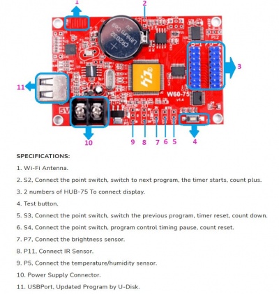

- I have bought a few led matrices (HUB12, 16x32 pixels, and HUB75, 64x64 at P3 and 64x128 at P2). HD-W60 modules allows animations to be loaded from a USB stick or be transmitted via Wifi. Animations are designed using the HD2016 (or 18 or 20) software (password is 168) or the "LedArt" phone application. Pretty neat (but completely useless...)
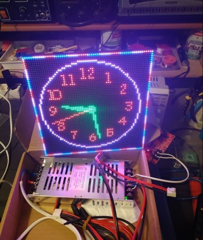
- I have bought a few led matrices (HUB12, 16x32 pixels, and HUB75, 64x64 at P3 and 64x128 at P2). HD-W60 modules allows animations to be loaded from a USB stick or be transmitted via Wifi. Animations are designed using the HD2016 (or 18 or 20) software (password is 168) or the "LedArt" phone application. Pretty neat (but completely useless...)
- Playing with the CubeCell LoRa enabled module.
- I have bought two CubeCell modules from Heltec (see here). These modules are fitted with a LoRa module and have a very low quiescent power consumption. Here is a picture of such module (bought on AliExpress):
- TRhose modules can be conected to a solar cell and a battery to ber fully autonomous.
- Unfortunately, I have bought 433MHz modules (read the order carefully before pressing "buy"...) that don't match my 868MHz Dragino. So I have hooked a SemTech SX1278 433 Mhz module to an ESP32 to check if those CubeCell actually work. See some doc here. As of today I have: one CubeCell that sends messages via LoRa, a ESP32 Wroom that receives it and advertise them via BLE serial...
- I have bought two CubeCell modules from Heltec (see here). These modules are fitted with a LoRa module and have a very low quiescent power consumption. Here is a picture of such module (bought on AliExpress):


November 2020
Playing with the Colorlight 5a-75b FPGA board. This very cleap FPGA board is used to control LED matrix panels. It is fitted for a Lattice ECP5 FPGA, a 32Mbits SPI flash, a 2MB 200MH SRDAM, and 2 Gigabits ethernet PHYs. The Lattice cheap is supported by a bunch of free development tools (synthesis, placement, bitstream generation).
See | Chubby75 page on the V8 version. This board can be bought on AliExpress for $12 or so. Here is a picture of the board:

August 2020
- Not much... I am trying to build a "Pulse counting FM demodulator". I use the circuit described (and expained) in (yet another) video from the excellent w2aew. The circuit is very simple: .
- Unfortunately, even tough I use the same components as w2aew, the behaviour of the circuit is not satisfying.
- So I have created a LTSPICE simulation to see if the simulation and the actual circuit behave in the same way. The analysis is given in this document.
July 2020
- I have bought (and played with) a bunch of RF components. See RF equipment.
- I am currently building a diode ring mixer. See the video about diode ring mixers by the excellent w2aew (check all videos, they are all great!). See also the one by Charlie Morris.
- Here is my homebrewed diode mixer:
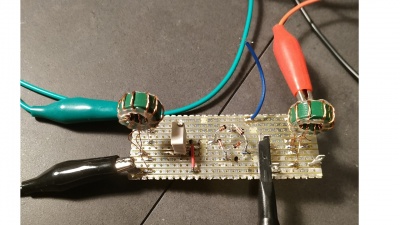
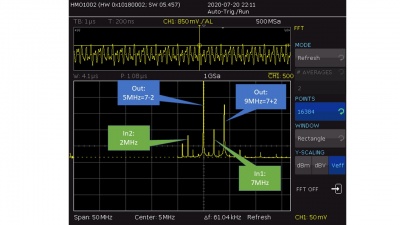
- A few pictures showing the spectrum of the signal obtained by mixing a 2MHz and a 7MHz signal.
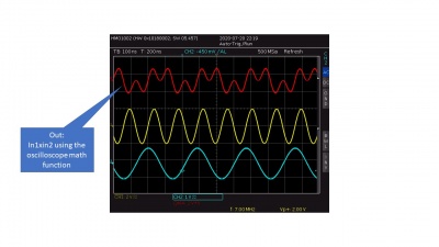
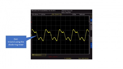
- And the mixed signal computed by the oscilloscope and mixed by the diode mixer:
- Here is my homebrewed diode mixer:
- I have watched the complete course about Python for IA by Machine Learnia (in french). Excellent!


June 2020
- Nothing.
May 2020
- May 3rd
- I have created a URDF model of the robot. This allows the automatic generation of the transformations (ROS' TF).
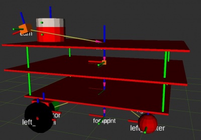
- The source files are here.
- The model is not aimed at being realistic: it only carries all the geometrical transformations between links (using joints).
- By the way, I try to describe what I do (more or less) in this document.
- I have created a URDF model of the robot. This allows the automatic generation of the transformations (ROS' TF).
- May 1st
- Still locked at home...
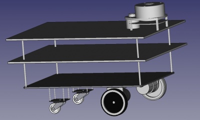
- I am curently creating a simple URDF model of my robot in order to generate transformations (from base link to the LIDAR, to the camera, etc.) automatically.
- So I have first modelled it (partially) with FreeCad:


April 2020
- April 18th
- I used to think that my Ender 5 was printing correctly... but no! By playing on the filament flow, I was able to prevent the head bumping on the printed surface. But the problem was NOT over-extrusion! The actual problem comes from the fact that there are two versions of the Ender5, with two different z-screw: one with 400 steps per cm and the other with 800 steps per cm. I own the second one but the default Marlin firmware for the Ender comes with the 400 steps / cm configuration (see file "Configuration.h", parameter "DEFAULT_AXIS_STEPS_PER_UNIT").
- So there were two solutions: either recompiling the firmware with the appropriate step per unit configuration, or using the "M92 Z800" directive.
- For the moment, I have simply changed the start G-code in Cura (Preferences/printers/Machine settings) and added "M92 Z800". Now, it seems that I am a bit underextruding. I have printed the calibration cube (here ) and the faces are far too thin with the current 75% flow.
- April 17th and before
- I am currently playing with Vue.js. My objective is to develop a small control interface for my robot. I have to say that building an HMI using Javascript and all the Web technologies is much much more efficient (in terms of development time) than using classical technologies! In a few hours (starting from a close-to-zero knowledge about Web techs), I have been able to create a small interface that displays the orientation of the robot in 3D (using three.js), plots some of its parameters (using Google Charts,) etc.
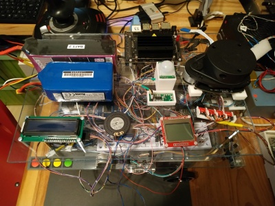
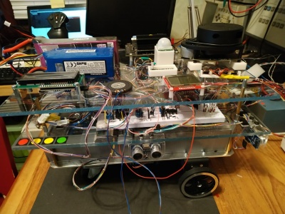
- UsineAGazBot,my robot has done its first steps!
- It is fitted with... 2 arduino pro mini, one arduino due, one arduino mega, one ESP32, one Raspberry Pi, one FPGA (Tang Nano), and one Jeston nano!, all these guys being connected via a CAN network.
- Surely, it is overkill, but I wanted to add functions one y one, incrementally, each of them beig hosted by its own CPU. Later, I'll try to make them fit in slightly less silicium.
- For the moment, it is completely remotely operated, but it is built using ROS and there shouln't be that many difficulties to make it autonomous.
- Here are a few pictures of the beast (I admit that it is difficult to find where's the front, where's the bottom...):
- I have finally managed to make my Ender 5 work: it was simply overextruding. By reducing the extrusion speed by 20%, it works just fine. I certainly have to calibrate the mm/step but, as it works... By the way, as my bed is not level, I use babystepping to ensure that the first layer sticks to the bed. This is manual, but not that complicated.


Mars 2020
- Covid 19 quarantine
- I have updated by Ender 5 3D printer with the latest version of Marlin. I have basically followed the indicated given by TeachingTech, here. I have had some difficulties when updating the firmware using the Arduino ISP. The trick was (i) to use a high quality USB cable, (ii) to place a 100uF capacitor between the reset pin and the ground on the Arduino. Once done, there was no problem to install the bootloader. Then I used the modified Marling configuration files proposed by TeachingTech. In order to add manual mesh leveling, I have uncommented the following #defines: MESH_BED_LEVELING, RESTORE_LEVELING_AFTER_G28 and LCD_BED_LEVELING in Configuration.h. Then I have commented ARC_SUPPORT (Configuration_adv.h) otherwise the binary was too big. And that's it.